Z8
®
CPU
User Manual
UM001604-0108 Input/Output Ports
66
I/O Port Reset Conditions
Full Reset
After a hardware reset, WDT reset, or a POR, Port Mode Registers P01M, P2M, and P3M
are set as displayed in Figure 54 on page 67 through Figure 56 on page 68. Port 2 is con-
figured for input operation on all bits and is set for open-drain (see Figure 55 on page 67).
If push-pull outputs are required for Port 2 outputs, remember to configure them using
P3M. Note that a WDT time-out from Stop Mode Recovery does not do a full reset. Cer-
tain registers that are not reset after Stop Mode Recovery will not be reset.
For the condition of the Ports after Stop Mode Recovery, refer to the specific device prod-
uct specifications. In some cases, Z8
®
MCU features the P01M, P2M, and P3M control
register set back to the default condition after reset while others do not.
All special I/O functions of Port 3 are inactive, with P33–P30 set as inputs and P37–P34
set as outputs (see Figure 56 on page 68).
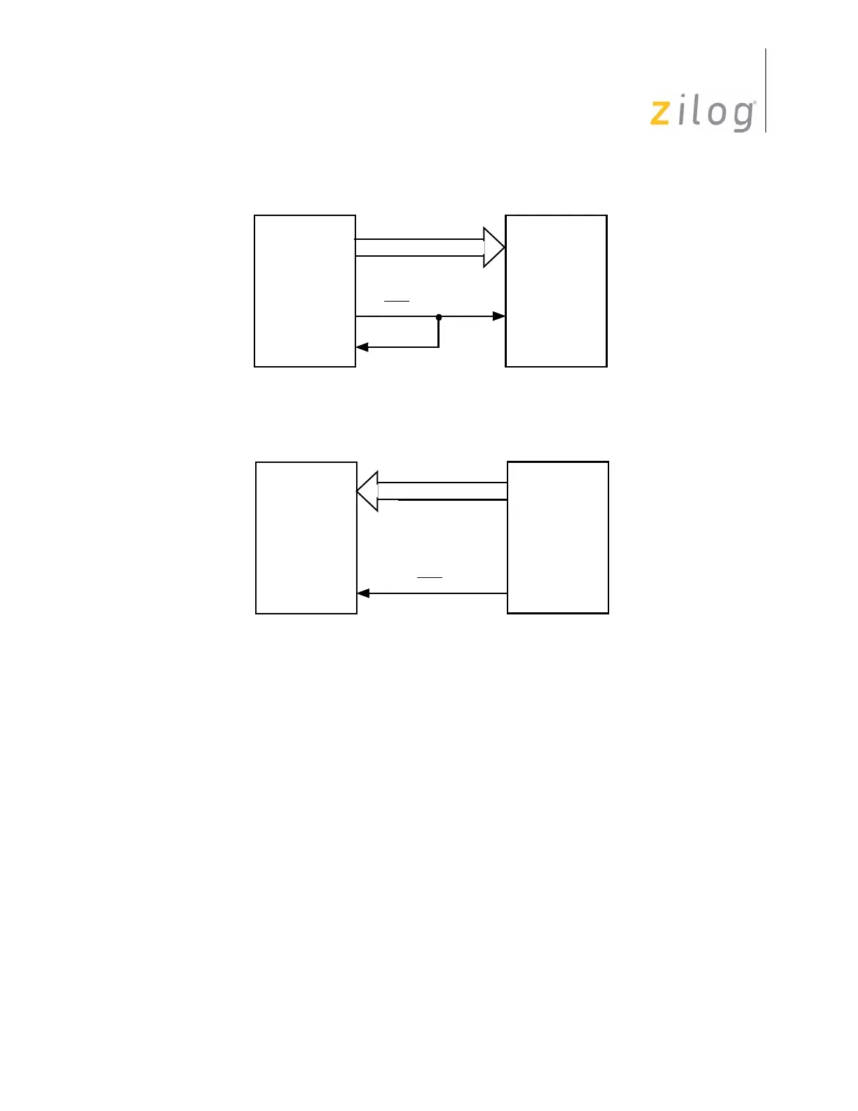
Figure 52. Output Strobed Handshake on Port 2
Figure 53. Input Strobed Handshake on Port 2
P36
Z8
P20–P27
P31
I/O
Device
DAV
RDY
Z8
P20–P27
P31
I/O
Device
DAV

 Loading...