Z8
®
CPU
User Manual
UM001604-0108 Input/Output Ports
51
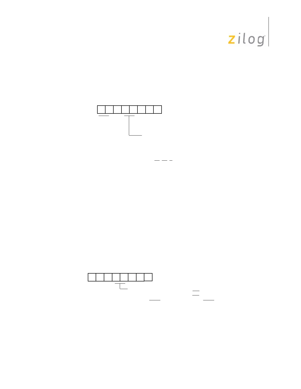
Using the Port 0–1 Mode Register, Port 1 is configured as an output port by setting bits D4
and D3 to 0, or as an input port by setting D4 to 0 and D3 to 1 (see Figure 36).
Handshake Operations
When used as an I/O port, Port 1 can be placed under handshake control by programming
the Port 3 Mode register bits D4 and D3 both to 1. In this configuration, handshake control
lines are DAV1 (P33) and RDY1 (P34) when Port 1 is an input port, or RDY1 (P33) and
DAV1 (P34) when Port 1 is an output port. See Figure 37 through Figure 39 on page 53.
Handshake direction is determined by the configuration (input and output) assigned to
Port 1. For example, if Port 1 is an output port then handshake is defined as output.
Figure 36. Port 1 I/O Operation
Figure 37. Handshake Operation
D4 D3
(F8, Write-Only)
Port 0–1 Mode Register
R248 P01M
01 = Byte Output
10 = AD0-AD7
00 = Byte Output
P10–P13 Mode
AS
, DS, R/W,
11 = High Impedance AD0–AD7,
A8–A11, A12–A15
D4 D3
(F7, Write-Only)
00 P33 = Input P34 = Output
01 P33 = Input P34 = DM
Port 3 Mode Register
R247 P3M
10 P33 = Input P34 = DM
11 P33 = DAV1
/RDY1 P34 = RDY1/DAV1

 Loading...