Z8
®
CPU
User Manual
UM001604-0108 Counters and Timers
88
T
IN
Modes
The Timer Mode Register TMR (F1h; see Figure 80 on page 89) is used in conjunction
with the Prescaler Register PRE1 (
F3h; see Figure 81 on page 89) to configure P31 as T
IN
.
T
IN
is used in conjunction with T1 in one of four modes:
•
External Clock Input
•
Gated Internal Clock
•
Triggered Internal Clock
•
Retriggerable Internal Clock
The T
IN
mode is restricted for use with timer 1 only. To enable the T
IN
mode selected (via
TMR bits 4-5), bit 1 of PRE1 must be set to 0.
The counter/timer clock source must be configured for external by setting the PRE1 Reg-
ister bit 2 to 1. The Timer Mode Register bit 5 and bit 4 can then be used to select the
appropriate T
IN
operation.
For T1 to start counting as a result of a T
IN
input, the Enable Count bit (bit 3 in TMR)
must be set to 1. When using T
IN
as an external clock or a gate input, the initial values
must be loaded into the down counters by setting the Load bit (bit 2 in TMR) to a 1 before
counting begins. In the descriptions of T
IN
that follow, it is assumed the programmer has
performed these operations. Initial values are automatically loaded in Trigger and Retrig-
ger modes so software loading is unnecessary.
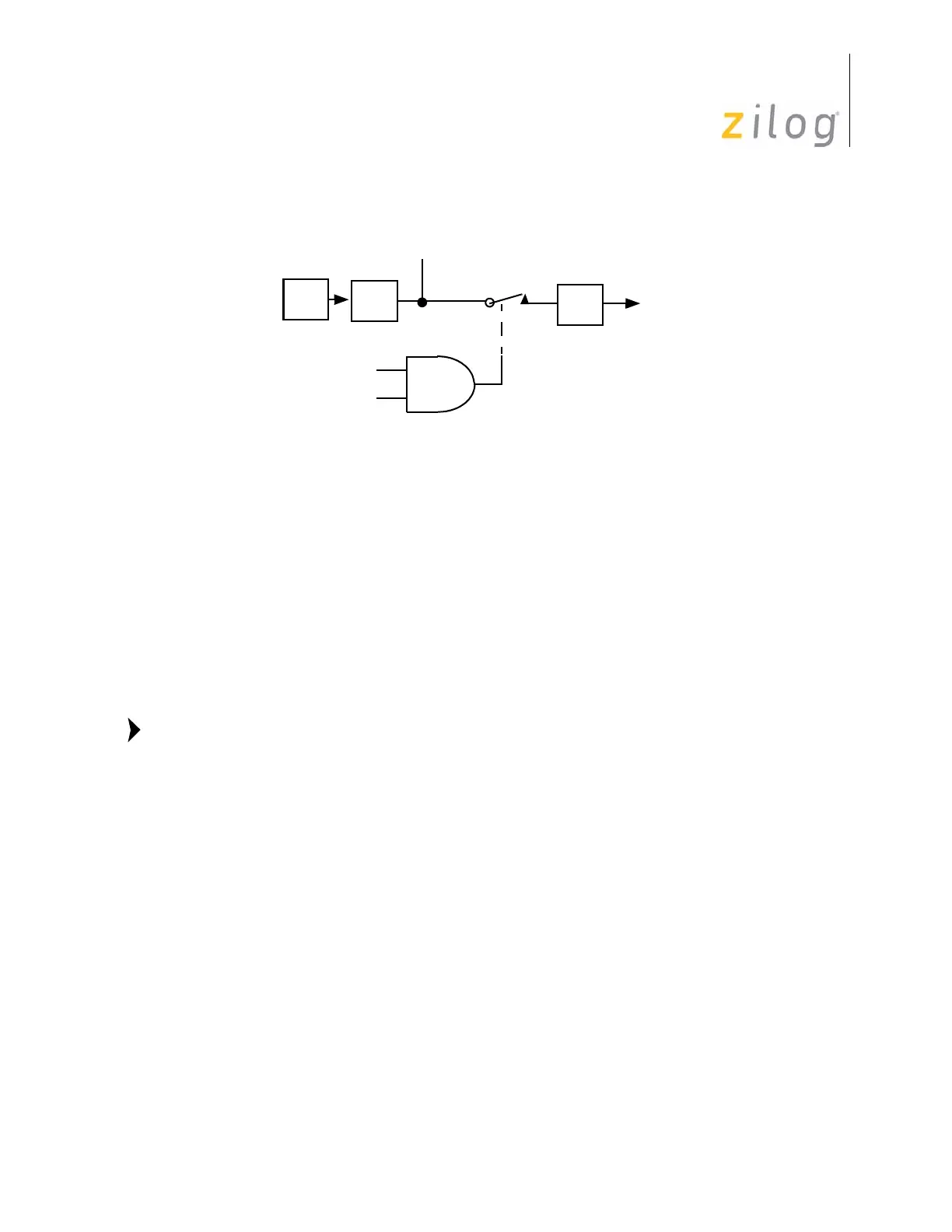
Figure 79. Internal Clock Output Through T
OUT
OSC
÷2
P3
6
T
OUT
Internal
TMR D
6
Clock
TMR D
7
Note:

 Loading...