Z8
®
CPU
User Manual
UM001604-0108 External Interface
133
Port 0 can be programmed to provide either four additional address lines (A11–A8), which
increases the addressable memory to 4 KB, or eight additional address lines (A15–A8),
which increases the addressable external memory up to 64 KB. It is required to add a NOP
after configuring Port 0/Port 1 for external addressing before jumping to external memory
execution.
External Stacks
Z8
®
CPU architecture supports stack operations in either the Z8 Standard Register File or
external data memory. A stack’s location is determined by bit 2 in the Port 0–1 Mode Reg-
ister (
F8h). If bit 2 is set to 0, the stack is in external data memory (see Figure 124 on page
134).
The instruction used to change the stack selection bit should not be immediately followed
by the instructions RET or IRET, because this causes indeterminate program flow. After a
RESET
, the internal stack is selected.
If Port 0 is configured as A15–A8 and the stack is selected as internal, any stack operation
causes the contents in register
FEh to be displayed on Port 0.
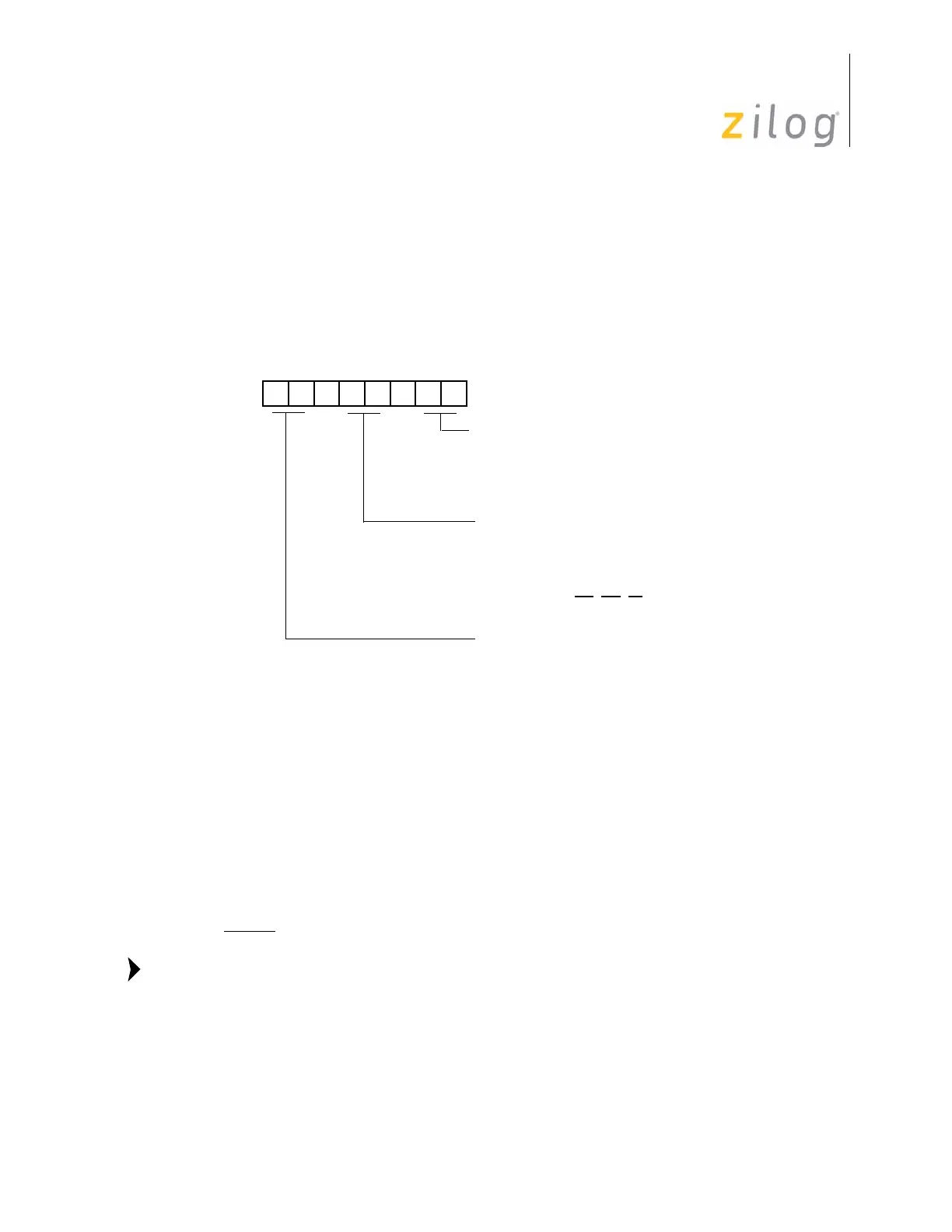
Figure 123. External Address Configuration
D7 D6 D5 D4 D3 D2 D1 D0
(Write-Only)
01 = Input
1X = A8–A11
P00–P07 Mode
00 = Output
Port 0–1 Mode Register (P01M)
Register F8h (P01M)
01 = Byte Output
P04–P07 Mode
00 = Output
01 = Input
1X = A12–A15
10 = AD0-AD7
00 = Byte Output
P10–P17 Mode
A8–A15, AS
, DS, R/W
11 = High Impedance AD0–AD7,
Note:

 Loading...