Z8
®
CPU
User Manual
UM001604-0108 Counters and Timers
86
Minimum duration is achieved by loading 01h (1 prescaler output count), maximum dura-
tion is achieved by loading
00h (256 prescaler outputs counts).
The prescaler and counter/timer are true divide-by-n counters.
T
OUT
Modes
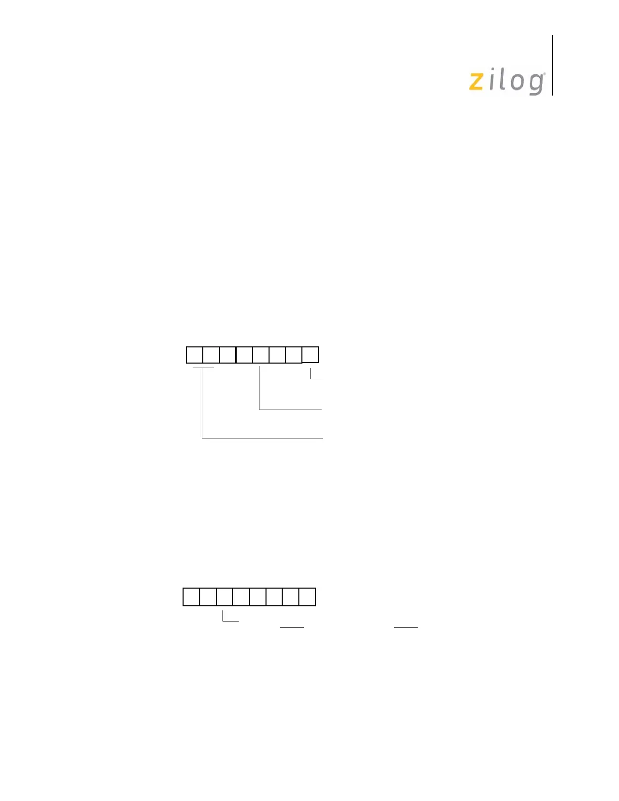
The Timer Mode Register TMR (F1h; see Figure 76), is used in conjunction with the Port
3 Mode Register P3M (
F7h; see Figure 77) to configure P36 for T
OUT
operation for T0
and T1. In order for T
OUT
to function, P36 must be defined as an output line by setting
P3M bit 5 to 0. Output is controlled by one of the counter/timers (T0 or T1) or the internal
clock.
The counter/timer to be output is selected by TMR bit 7 and bit 6. T0 is selected to drive
the T
OUT
line by setting bit 7 to 0 and bit 6 to 1. Likewise, T1 is selected by setting bit 7
Figure 76. Timer Mode Register (T
OUT
Operation)
Figure 77. Port 3 Mode Register (T
OUT
Operation)
D7 D6 D3 D0
(Read/Write)
0 = No Function
1 = Load T
0
Timer Mode Register (TMR)
Register F1hR
T
OUT
Modes:
0 = Disable T
1
Count
1 = Enable T
1
Count
T
OUT
OFF = 00
T
0
OUT = 01
T
1
OUT = 10
Internal Clock OUT = 11
D7 D6 D5 D4 D3 D2 D1 D0
(Write-Only)
Port 3 Mode Register (P3M)
Register F7h
0 P31 = Input (T
IN
) P36 = Output (T
OUT
)
1 P31 = DAV2
/RDY2 P36 = RDY2/DAV2

 Loading...