Z8
®
CPU
User Manual
UM001604-0108 Counters and Timers
89
It is suggested that P31 be configured as an input line by setting P3M Register bit 5 to 0,
although T
IN
is still functional if P31 is configured as a handshake input.
Each High-to-Low transition on T
IN
generates an interrupt request IRQ2, regardless of the
selected T
IN
mode or the enabled/disabled state of T1. IRQ2 must therefore be masked or
enabled according to the requirements of the application.
External Clock Input Mode
The T
IN
External Clock Input Mode (TMR bit 5 and bit 4 both set to 0) supports counting
of external events, where an event is considered to be a High-to-Low transition on T
IN
(see Figure 82).
See the product data sheet for the minimum allowed T
IN
external clock input period (T
P
T
IN
).
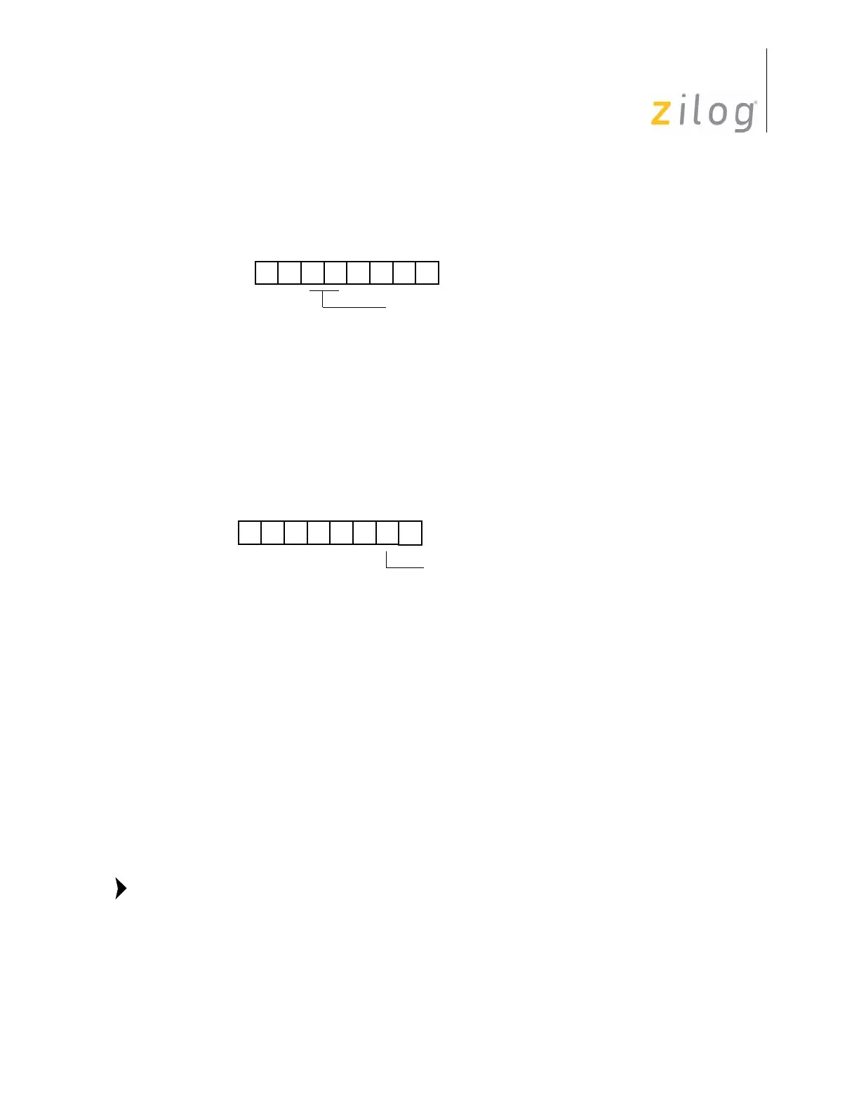
Figure 80. Timer Mode Register (T
IN
Operation)
Figure 81. Prescaler 1 Register (T
IN
Operation)
D5 D4
(Read/Write)
Timer Mode Register (TMR)
Register F1h
(Retriggerable)
(Non-retriggerable)
Trigger Input = 10
T
IN
= Modes:
External Clock Input = 00
Gate Input = 01
Trigger Input = 11
D7 D6 D5 D4 D3 D2 D1 D0
(Write-Only)
1 = T
1
Internal Disable T
IN
Mode
Clock Source
0 = T
1
External Enable T
IN
Mode
Prescaler 1 Register (PRE1)
Register F3h
Note:

 Loading...