Z8
®
CPU
User Manual
UM001604-0108 External Interface
131
External Interface
Introduction
Z8
®
CPU
can be a microcontroller with 20 pins for external memory interfacing. The
external memory interface on the Z8 CPU is generally for either RAM or ROM; this fea-
tures is only available for devices featuring Port 0, Port 1, R/W
, DM, AS, and DS. Refer to
specific product specifications for availability of these features.
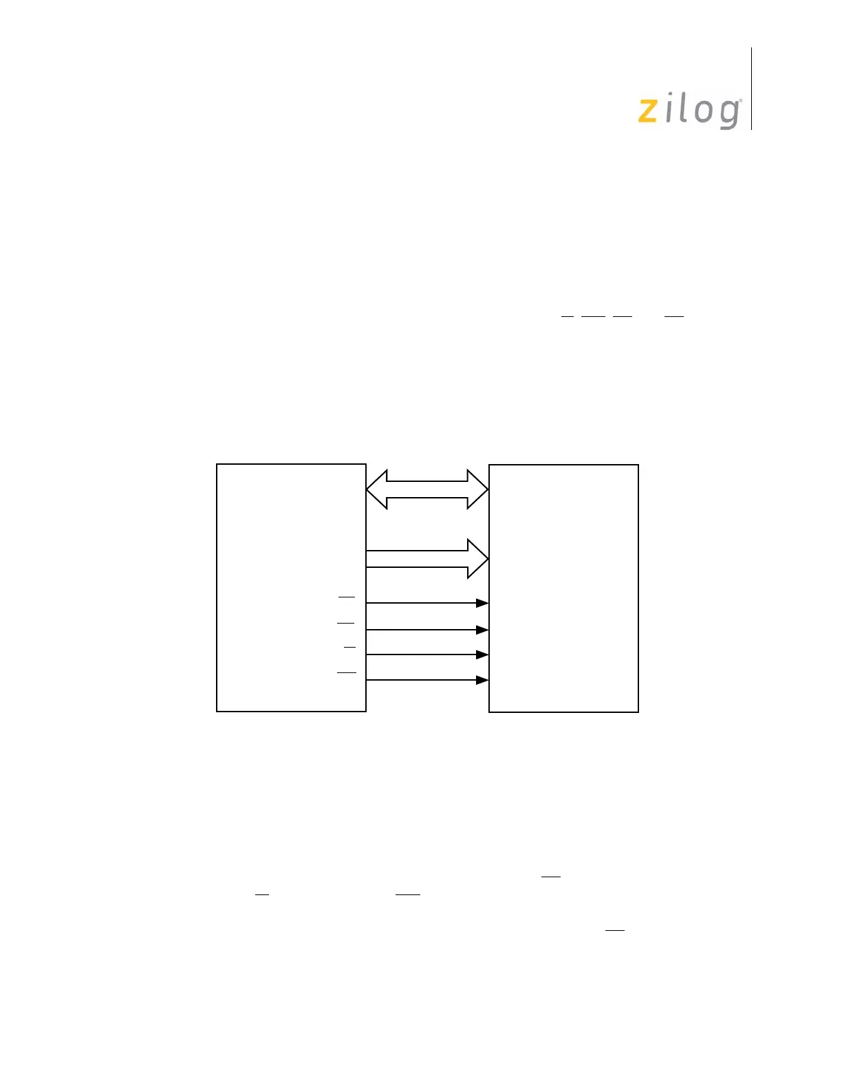
Z8 CPU offers a multiplexed external memory interface. In multiplexed mode, eight pins
from Port 1 form an Address/Data Bus (AD7–AD0), eight pins from Port 0 form a High
Address Bus (A15–A8). Three additional pins provide the Address Strobe, Data Strobe,
and the Read/Write Signal. Figure 122 displays the Z8 CPU external interface pins.
Pin Descriptions
The following sections briefly describe the pins associated with the Z8 CPU external
memory interface.
Address Strobe (output, active Low)—Address Strobe (AS) is pulsed Low once at
the beginning of each machine cycle. The rising edge of AS
indicates the address, Read/
Write (R/W
), and data memory (DM) signals are valid for program or data memory trans-
fers. In some cases, the Z8 CPU address strobe is pulsed low regardless of accessing exter-
nal or internal memory. Refer to specific product specifications for AS
operation.
Figure 122. Z8 CPU External Interface Pins
External
Z8
®
CPU
Program/Data
64KB
Each
(Port 1) AD7–AD0
(Port 0) AD15–AD8
AS
DS
R/W
DM

 Loading...