Z8
®
CPU
User Manual
UM001604-0108 Serial Input/Output
122
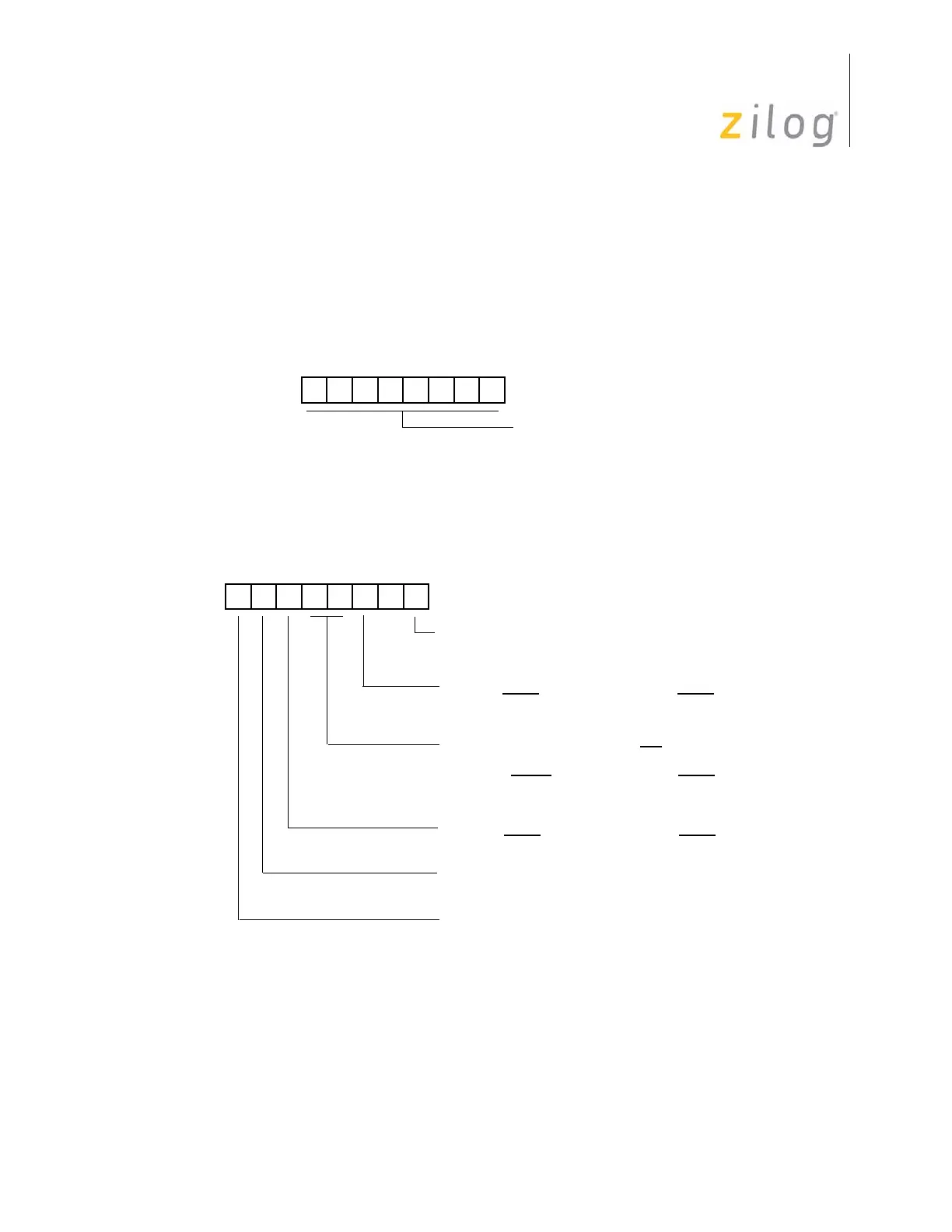
UART Reset Conditions
After a hardware reset, the SIO Register contents are undefined, and Serial Mode and par-
ity are disabled. Figure 114 and Figure 115 display the binary reset values of the SIO Reg-
ister and its associated mode register P3M.
Serial Peripheral Interface
Select Z8 microcontrollers incorporate a Serial Peripheral Interface (SPI) for communica-
tion with other microcontrollers and peripherals. The SPI includes features such as Stop-
Figure 114. SIO Register Reset
Figure 115. P3M Register Reset
U U U U U U U U
(Read/Write)
Serial Data (D
0
= LSB)
Serial I/O Register (SIO)
Register RF0h
0 0 0 0 0 0 0 0
(Write-Only)
0 P32 = Input P35 = Output
1 P32 = DAV0/RDY0 P35 = RDY0/DAV0
0 Port 2 Pull-Ups Open-Drain
1 Port 2 Pull-Ups Active
00 P33 = Input P34 = Output
01 P33 = Input P34 = DM
Port 3 Mode Register (P3M)
Register F7h
10 P33 = Input P34 = DM
11 P33 = DAV1/
RDY1 P34 = RDY1/DAV1
0 P31 = Input (T
IN
) P36 = Output (T
OUT
)
1 P32 = DAV2/RDY2 P36 = RDY2/DAV2
0 P30 = Input P37 = Output
1 P30 = Serial In P37 = Serial Out
0 Parity ON
1 Parity OFF

 Loading...