Z8
®
CPU
User Manual
UM001604-0108 Instruction Description
161
Add With Carry
Syntax
ADC dst, src
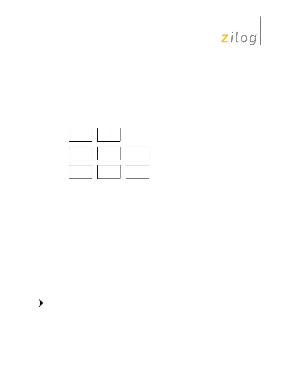
Instruction Format
Operation
dst ← dst + src + C
The source operand, along with the setting of the Carry (C) Flag, is added to the destina-
tion operand. Two’s complement addition is performed. The sum is stored in the destina-
tion operand. The contents of the source operand are not affected. In multiple precision
arithmetic, this instruction permits the carry from the addition of low order operands to be
carried into the addition of high order operands.
Address modes R or IR can be used to specify a 4-bit Working Register. In this format, the
source or destination Working Register operand is specified by adding
1110b (Eh) to the
high nibble of the operand. For example, if Working Register R12 (CH) is the destination
operand, then
ECh is used as the destination operand in the Op Code.
Cycles
OPC
(Hex)
Address
Mode
dst src
OPC dst src
602rr
603rlr
OPC src dst
10 04 R R
10 05 R IR
OPC dst src
10 06 R IM
10 07 IR IM
Flag Description
C Set if there is a carry from the most significant bit of the result; cleared otherwise.
Z Set if the result is zero; cleared otherwise.
S Set if the result is negative; cleared otherwise.
V Set if an arithmetic overflow occurs, that is, if both operands are of the same sign
and the result is of the opposite sign; cleared otherwise.
D Always cleared.
H Set if there is a carry from the most significant bit of the low order four bits of the
result; cleared otherwise.
Note:

 Loading...