Z8
®
CPU
User Manual
UM001604-0108 Instruction Description
221
Rotate Left Through Carry
Syntax
RLC dst
Instruction Format
Operation
C← dst(7)
dst(0) ← C
dst(1) ← dst(0)
dst(2) ← dst(1)
dst(3) ← dst(2)
dst(4) ← dst(3)
dst(5) ← dst(4)
dst(6) ← dst(5)
dst(7) ← dst(6)
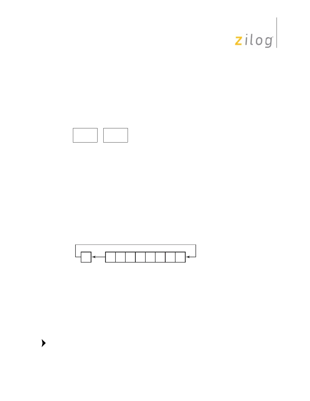
The contents of the destination operand along with the C Flag are rotated left by one bit
position. The initial value of bit 7 replaces the C Flag and the initial value of the C Flag
replaces bit 0, as shown below.
Address modes R or IR can be used to specify a 4-bit Working Register. In this format, the
destination Working Register operand is specified by adding
1110b (Eh) to the high nibble
Cycles
OPC
(Hex)
Address Mode
dst
OPC dst
610 R
611 IR
Flag Description
C Set if the bit rotated from the most significant bit position was 1
(i.e., bit 7 was 1).
Z Set if the result is zero; cleared otherwise.
S Set if the result bit 7 is set; cleared otherwise.
V Set if arithmetic overflow occurred (if the sign of the destination
operand changed during rotation); cleared otherwise.
D Unaffected
H Unaffected
C D7D6D5D4D3D2D1D0
Note:

 Loading...