8.3.1.4. Mounting the front part
¾ Place the front part of housing onto the lower part and fix them with 2x Allen cylinder screws (M4x10mm)
located at the bottom of the device (lower part of housing)
¾ Plug all cables to the mainboard
¾ Mount the rear part of housing (see 8.3.1.2)
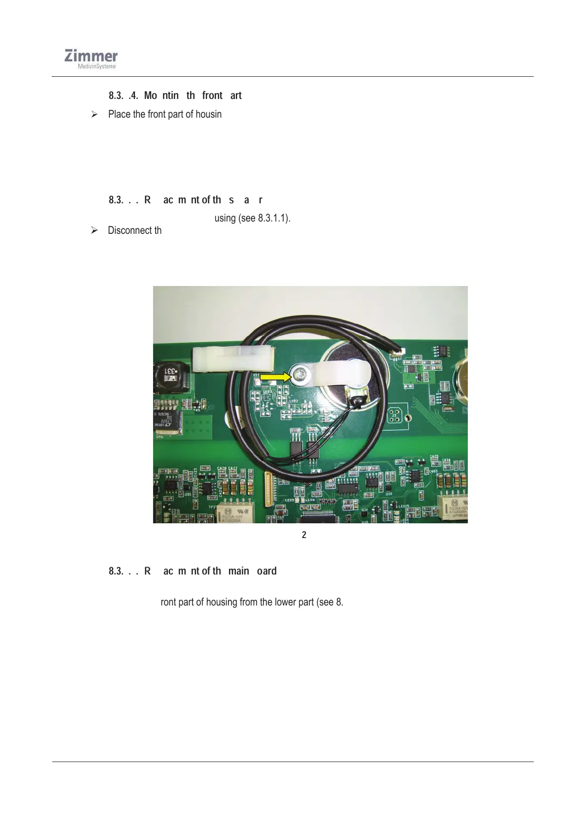
8.3.1.5. Replacement of the speaker
¾ Opening the rear part of housing (see 8.3.1.1).
¾ Disconnect the speaker cable from the mainboard
¾ Unscrew the Screw (PT EJOT 3,0x8 mm) and remove the holder
¾ Now the speaker can be taken out and be changed.
¾ After changing the speaker mount the cover (see 8.3.1.2).
Figure 21
8.3.1.6. Replacement of the main board
¾ Opening the rear part of housing (see 8.3.1.1)
¾ Remove the front part of housing from the lower part (see 8.3.1.3)
¾ Disconnect all cables from the main board
¾ Detach the main board from the distance bolts. Therefore unscrew the 4x screws (M3x6mm)
¾ Now remove the mainboard from the housing
¾ Placing the new board onto the distance bolts, and screw the 4x screws
¾ Connect all cables to the mainboard.
¾ Mount the front part and rear part of housing to the lower part ( see 8.3.1.2, 8.3.1.4)
¾ Run a function check (use the Safety check in chapter 12)