6. Electronic
6.1. Overview
6.1.1. Electronic description of the PhySys Edition SD device
The whole electronic hardware of the PhySys Edition SD is placed on 2x boards.
The first board (mainboard) contains the power supply for the processor and DSPs, the periphery operating section for
the graphical- and acoustic signals, for the touch controller, components for operating the actuators, the stimulation
current signal generation components and the ultrasonic generation components. Further the electrical circuits for the
monitoring of the stimulating currents and voltages and relays for switching of the setting channels are also integrated on
this board.
The second board is the power supply board, which contains a wide-range switching power supply unit for a voltage
range between (90V to 275V). All device external connectors for the stimulating currents and ultrasonic therapy are also
located on this board. Several connecting cables realize the communication between these two boards.
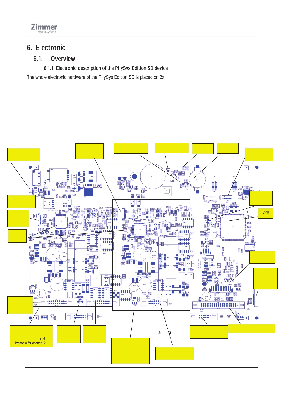
The next figures show the various circuit sections and components on the main board.
Figure 6: Top view of the mainboard
PCB-block to generate
and regulate the patient
stimulating current and
ultrasonic for channel 2
CPU
Touch screen
connection
Battery
PCB-block to
generate and regulate
the patient stimulating
current for channel 1
EEPROM
Real Time Clock
Backlight
connection
JTAG
(Debug CPU)
Watchdog
jumper
Audio connection
User Vaco
connection
User
Display
connection
User Control Connection
Connection for
actuator board
User PC 1
(Stimulating current)
User PC1
(Ultrasonic)
User PC0
(Stimulating
current)
Ultrasonic
output
DSPs
JTAG
(Debug
DSP2)
JTAG
(Debug DSP1)