6.1.2. Electronic description of the VacoP device
The electronic of the VacoP device is placed on the mainboard.
A connecting cable to the PhySys Edition SD device supplies the VacoP with the mains voltage.
A mains fuses 0,2AT (230-240V device) or 0,4A (100-120V device) are integrated in a fuse-holder which placed at the
VacoP housing. This fuse is dimensioned apt to the VacoP performance, which interrupts the power supply in case of
over-current or in case of failure. From here the mains voltage is distributed via cable to the mains voltage section on the
mainboard. In this path are 4 jumpers integrated, which can switch the transformer input voltage between 115V or 230V.
The low-voltage part on the mainboard starts at the secondary side of the transformer, which generates the necessary
voltage of 12V for operating the pump and the valve.
Furthermore the required voltage of 5V for operating the pressure sensor and the water level sensor is directly achieved
by connecting cable to the PhySys Edition SD device.
All device functions, regulation and monitoring are controlled directly by the PhySys Edition SD CPU
.
The communication between the devices is realized by connecting cable. As signal inputs and outputs of the VacoP are
the signals to control the pressure valve (A (12V) / off (0V)), control of the pump (A (12V) / Off (0V)) and the signals for
monitoring the pressure (ADC_Press from 0 to 5V) and the level of the water (no liquid 0V / 5V).
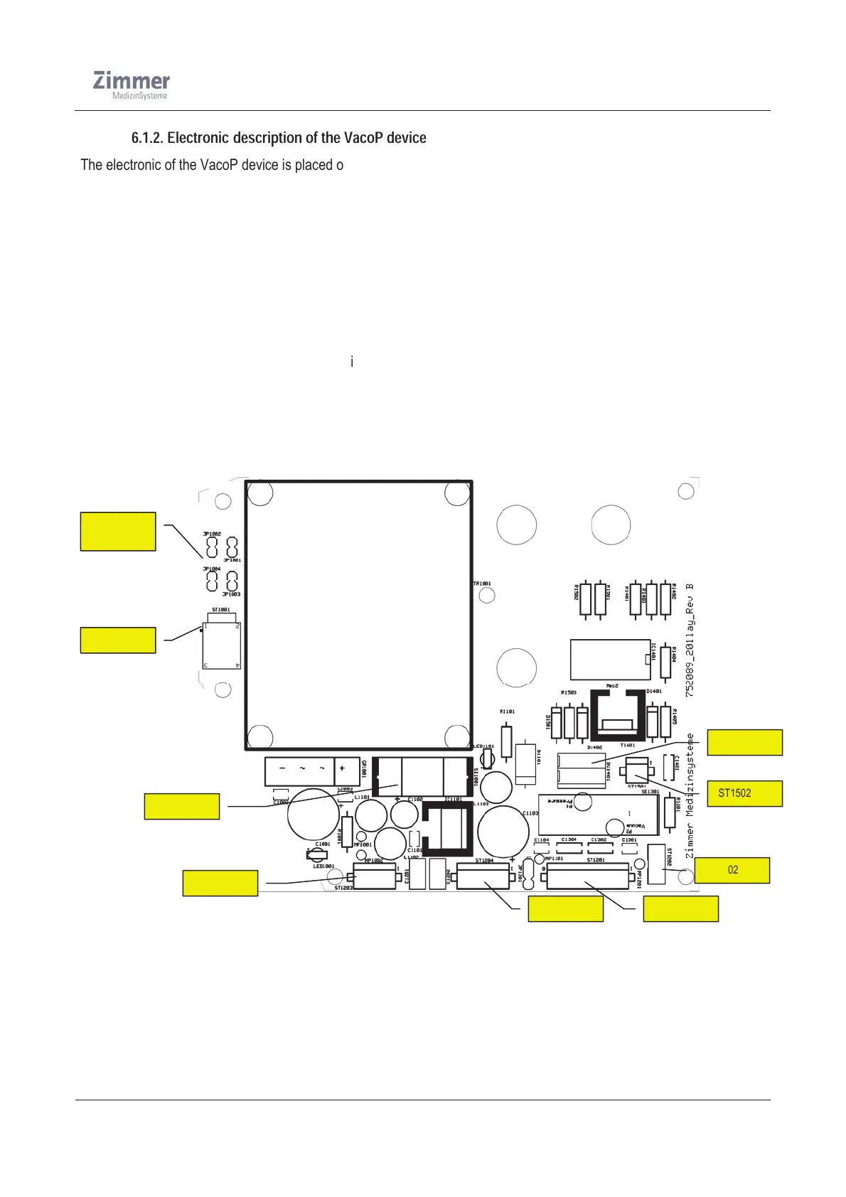
The next figure show the mainboard of the VacoP device
Figure 11
JP1001