Installation Guide for the 2GIG EDGE Security Panel
18
Connect the Hardwire Loops
The 2GIG EDGE Panel supports up to two (2) wired zones. Typically, these zones are used for hardwired Door/Window contact sensors. You rst
install the contact sensors and then route the loop wiring to the 2GIG EDGE Panel. This type of connection is commonly referred to as hardwire
loops.
IMPORTANT: The hardwire loops on the 2GIG EDGE Panel are designed to support contact sensors such as magnetic reed switches
or pressure pads. They are not designed for hardwire smoke detectors, carbon monoxide detectors, motion detectors, or glass break
detectors.
TIP: If you are planning to upgrade the existing wired security system at the home or business to a wireless system or if you have a
need to retrot any pre-wired sensors in newer construction for wireless, you can purchase the 2GIG Hardwire Conversion Kit ( 2GIG-
TAKE-KIT1) .
To install the hardwire loop wiring for the contact sensors:
1. Install the wired contact sensors.
2. Route the contact sensor’s loop wire(s) through the wiring cutout in the back of the 2GIG EDGE Panel.
3. Use the diagram below as a guide for connecting the sensor’s loop wires to the terminal block on the 2GIG EDGE Panel.
»
Normally Closed (N/C): Used for Normally Closed (N/C) circuits. This means the circuit on the contact switch is closed when the
magnets are aligned on the door/window contact. When armed, the 2GIG EDGE Panel activates an alarm signal when it detects that the
door or window is no longer in the normally closed state.
»
Normally Open (N/O): Used for Normally Open (N/O) circuits. This means the circuit on the contact switch is open when the magnets
are aligned on the door/window contact. When armed, the 2GIG EDGE Panel activates an alarm signal when it detects that the door or
window is no longer in the normally open state.
»
End-of-Line Resistor (EOLR): Used to supervise the sensor for open or short circuit conditions with an End- of-Line Resistor
(EOLR). If EOLR supervision is required, you must install a 2.2 kΩ resistor (not supplied). End of Line Resistors must be installed at the
location in the loop farthest away from the panel. This feature allow for the use of an EOL resistor for existing zones.
NOTE: For compliance with UL 38: Manual Signaling Boxes for Fire Alarm Systems, stranded conductors clamped under wire binding
screws or similar parts shall have the individual strands soldered together or shall be equivalently arranged.
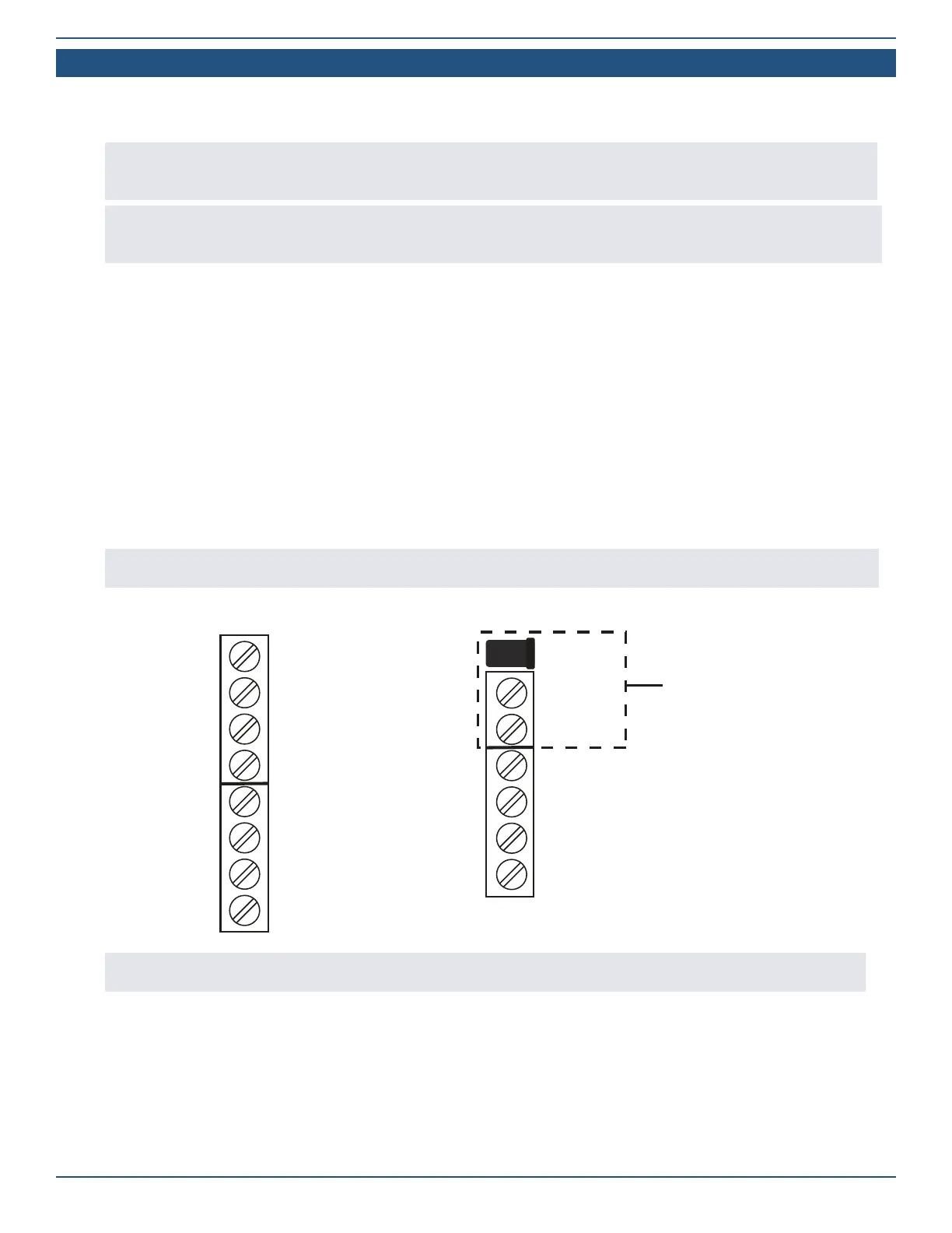
Wiring Diagram — Hardwire Loops
GND
AUX+
GND
Bell +
Bell –
Zone 1
Zone 2
GND
DC IN
DC IN +
DC IN –
OCL 1
OCL 2
TX
RX
POWER IN
TIP: After the installation is complete, you must program the wired zone into the 2GIG EDGE Panel. During programming, you must
dene the normal state of the circuit for each wired zone. See “Program a Wired Zone.”