Copyright © 2022 Nortek Security & Control LLC
23
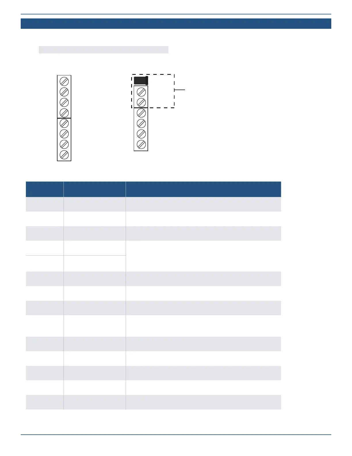
Terminal Blocks Wiring Diagram
The 2GIG EDGE Panel includes an 8-position terminal block and a 6-position terminal block. The table below describes each position on the
terminal blocks.
NOTE: Terminal block accommodates up to 18 gauge wire.
Terminal Block Positions*
GND
AUX+
GND
Bell +
Bell –
Zone 1
Zone 2
GND
DC IN
DC IN +
DC IN –
OCL 1
OCL 2
TX
RX
POWER IN
1
2
3
4
5
6
7
8
9
10
11
12
13
14
Position Label Description
1 GND (DC OUT–)
GND (DC OUT–)
2 AUX+ 5VDC @500mA Max
3 GND Ground (Low Side Hardwire Zone)
4 Bell +
5-14VDC @ 200mA Max
NOTE: Bell Output is only active when the 2GIG Edge Panel is powered
by the AC power source.
5 Bell –
6 ZONE 1 Hardwire Loop Zone 1
7 ZONE 2 Hardwire Loop Zone 2
8 GND Ground (Low Side Hardwire Zone)
9* DC IN +
14 VDC Power Input (+). Only provides power when the panel’s power
supply is connected to an AC power source.
10* DC IN – 14 VDC Power Input (–)
11 OCL 1 Open Collector Output 1
12 OCL 2 Open Collector Output 2
13 TX Image Sensor TX
14 RX Image Sensor RX