Technical Information DFS 700 / 04.2009 4-2
A corresponding light sensor (Figure 3-1 Item 2) is located in the upper field of the central
figure.
With two independent thresholds the display can also be set to flashing and an additional
external device, e.g. a flashing warning light, can be switched on for an additional warning
The speed-display unit can store up to 100,000 measurements. If the memory is full additional
measurements will overwrite the oldest measurements first.
All the settings for operation of the speed-display unit are made using the DFS-CAS user
program. The DFS-CAS user program can be installed on a PC running the Windows XP/2000
operating system and/or on a PDA running Windows Mobile 5.0.
The connection from the display unit to the PC is created using the USB-cable supplied
(Figure 3-2 Item 7) or, after activating the supplied Bluetooth adapter (Figure 3-2 Item 6) on
the PC by wireless connection. A Bluetooth-capable PDA can also be connected wireless to
the display unit.
Where the optional GSM-Modem (Figure 3-3 Item 4) is used, additional radio communication
is possible via the GSM network (mobile communication). To that end a modem is needed in
the PC and a GSM-SIM-card (Figure 3-3 Item 4B) is required in the GSM-modem (see also
4.5).
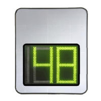
The speed display unit has a 2 1/2 LED digital display, which can display the maximum value
199. It comprises a total of 27 light segments homogenously tuned to each other (13
segments per number, 1 segment for the leading 1). Under optimum environmental conditions
the digits can be read at a distance of over 100 m.
The operating elements and electrical connections (see Figure 4-1) are located on the back of
the speed display unit under a two-part service cover (Figure 3-1 Items 11 and 12).
The connected cables are held in place by a foam rubber seal after the service covers are in
place.
The speed display unit has passive internal ventilation provided by two add-on vents (Figure
3-1 Item 8). The vents must always be kept uncovered.