Technical Information DFS 700 / 04.2009 4-3
5
6
7
8
9
11 10
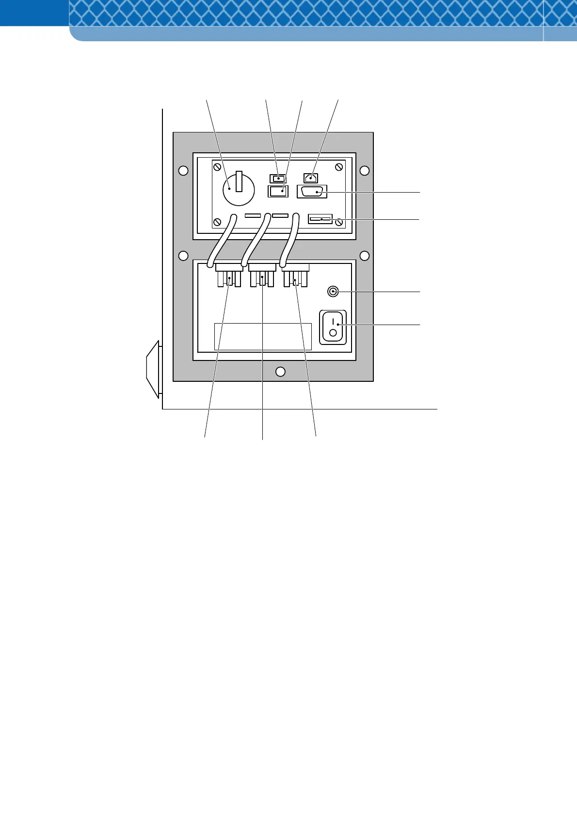
Figure 4-1 Operating elements and electrical connections
1 Buffer battery for real-time clock
2 Plug connector for power to the GSM/GPRS Modem
3 Plug connector for externally controllable device (e.g. flashing warning light)
4 USB-plug connector
5 RS 232 plug connector for GSM/GPRS Modem data cable
6 Flat fuse 4A delay action
7 Grounding bolts for connecting to a ground cable or a protective cable
8 DFS 700 on/off main-switch
9 Plug connector for optional 12V power from the 230 V Power Supply Unit box or
second optional Battery (is not powered by the Battery Charger)
10 Plug connector for the first optional Battery (is powered by the Battery Charger)
11 Plug connector for optional Battery Charger