Technical Information DFS 700 / 04.2009 6-4
2
x2
5
3
1
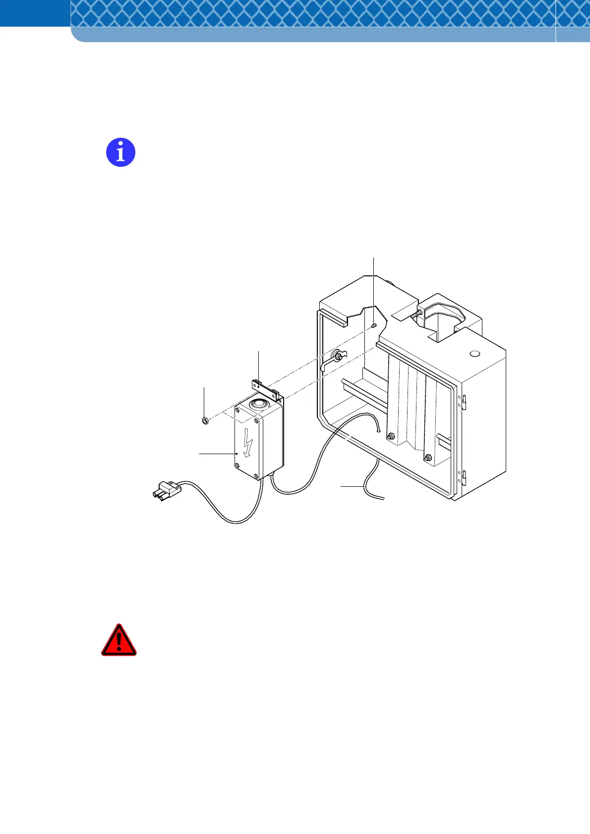
6.3 Preliminary work on the DFS 700 with optional accessories
Fitting the 230V Power Supply Unit box into Battery- & Mounting Box
Where the Battery- & Mounting Box is available, the Power Supply Unit box (Figure 6-4
Item 1) can be fitted into the Battery- & Mounting Box instead of connecting it to the
frame.
(1) Push the Power Supply Unit box with the free mounting plate holes (Figure 6-4 Item 3)
onto the two bolt threads (Figure 6-4 Item 4) on the left in the Battery- & Mounting Box
and tighten fully with two M4 hexagonal bolts (Figure 6-4 Item 2).
Figure 6-4 Fitting the Power Supply Unit box
(2) Create an opening in the base of the Battery- & Mounting Box for the power cable
(Figure 6-4 Item 5) and pull the power cable through the opening, which should be
sealed with a PG-seal.
Only qualified electricians are allowed to carry out this work, see safety advice in
section 2. Risk of injury from electric shock in case of unqualified assembly!