Technical Information DFS 700 / 04.2009 6-3
1
2
3
4
6
7
8
2
3
3
4
3
2
x2
x2
5
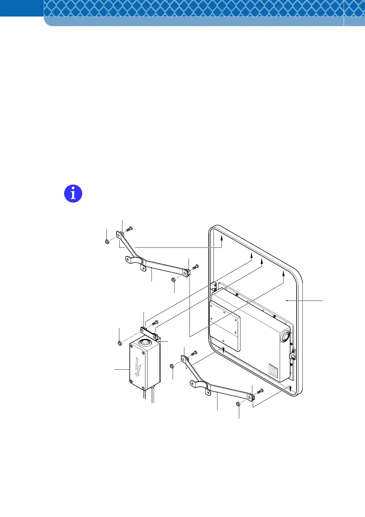
6.2 Preliminary work on the standard model DFS 700
(1) Push the two clamps (Figure 6-3 Item 2) of the mounting brackets (Figure 6-3 Item 4)
into the frame (Figure 6-3 Item 1) on the top and bottom side in each case. Use the
longer one on the top.
(2) Tighten the four hexagonal nuts fully (Figure 6-3 Item 3) and check if the mounting
bracket is seated securely.
(3) Set the fixing plate (Figure 6-3 Item 5) of the optional Power Supply Unit box (Figure 6-3
Item 6) centrally in the frame on the top side and insert the two clamps (Figure 6-3 Item
7).
(4) Tighten the two hexagonal nuts fully (Figure 6-3 Item 8) and check if the Power Supply
Unit box is seated securely.
If required, the Power Supply Unit box can also be set up separately keeping the same
vertical alignment.
Figure 6-3 Attachment of the mounting brackets and Power Supply Unit box