Technical Information DFS 700 / 04.2009 7-12
3
4
67
2
1
8
5
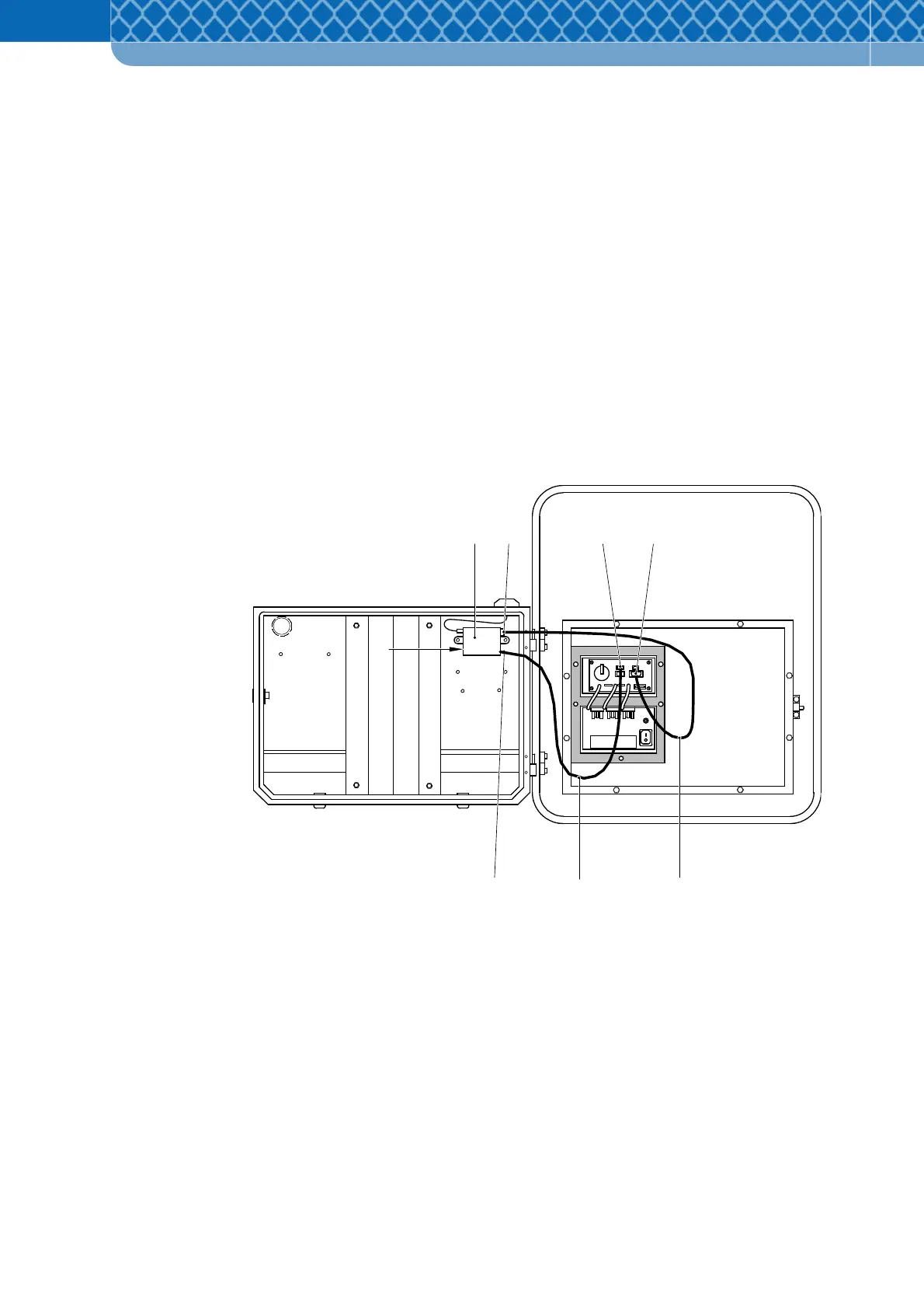
7.3.5 Power supply to the GSM/GPRS Modem
If the GSM/GPRS Modem is used, the following work has to be carried out in addition before
the DFS 700 is switched on.
(1) Remove both service covers on the DFS 700.
(2) Insert the activated SIM-card (Figure 7-10 Item 1) into the modem (Figure 7-10 Item 2), if
this has not already been done. See also section 4.5.
(3) Plug the power supply cable (Figure 7-10 Item 6) into the connection socket of the GSM
modem (Figure 7-10 Item 7) and the other plug into the socket on the DFS (Figure 7-10
Item 3).
(4) Connect the GSM-data cable (Figure 7-10 Item 5) to the sockets on the DFS and GSM
Modem (Figure 7-10 Item 8 and 4) and tighten them.
Figure 7-10 Connect the GSM/GPRS Modem
(5) Approx. 10 seconds after switching on the DFS 700 the LED on the side of the modem
should flash - the modem is then registered in the mobile network. If the LED lights
continuously, check the PIN entry and correct it if required.
The modem is ready for use approx. 40 seconds after switching on the
DFS 700.