Technical Information DFS 700 / 04.2009 4-10
2
3
4
5
5
6
7
x2
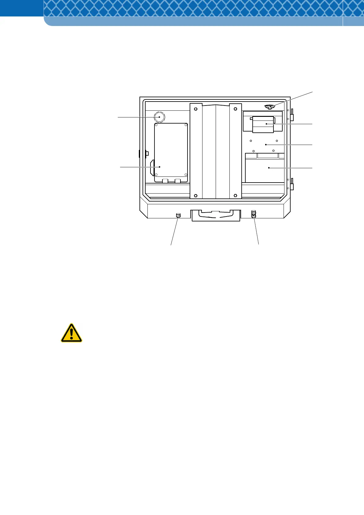
On the top of the box there is a sealed cover for the GSM antenna (Figure 4-5 Item 1).
On the bottom of the box openings have been prepared, into which a PG gasket can be
inserted if necessary for safe and tight guiding of the cables of the Power Supply Unit box
(Figure 4-5 Item 6) or Battery Charger (Figure 4-5 Item 3).
Figure 4-5 Positions of accessories and components
1 Opening for GSM antenna
2 GSM/GPRS-Modem
3 Space for Battery Charger
4 Battery
5 Openings for PG screwed joints
6 Power Supply Unit box or Battery
7 Ventilation opening
Only a qualified electrician may carry out this work! Risk of injury as a result of electric
shock!
The Battery- & Mounting Box is attached to a holding pole by the clamping frame (Figure 4-4
Item 1) which is fixed tight to the box by four bolts.