16
M512-3 Juggler : User Guide
© 2021 7thSense
Rear Panel Connections
Rear Panel Connections
The back panel of each Juggler is factory configurable to order. The required number and type of
inputs and outputs for a system of Jugglers is expandable by adding Juggler modules as required.
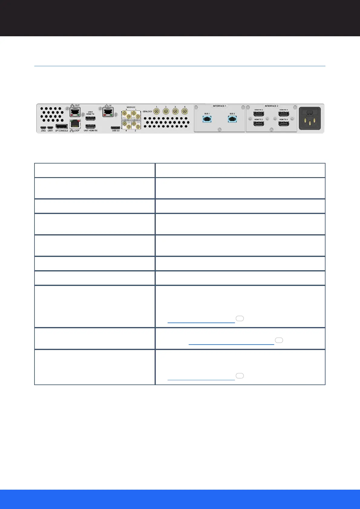
Working from left to right, these connections are available:
Service use only. Connection for Juggler Console to address the
FPGA processor.
Non-user Ethernet ports relating to front panel control, always
connected to each other. (LEDs on OUT are inactive.)
Used in Juggler modules configured for HDMI, expandable with the
I/O Interface panels.
Network port (LEDs on this port are inactive).
MODULE × 4, numbered 1-4 (options)
4 × SFP modules,
either 12G bidirectional coax (12G-SDI HD-BNC)
or optical fibre (LC) for SDI or to form a 4-lane (‘half’) bus between
Juggler modules
see Connect a Juggler Data Bus
GENLOCK / GPIO – 4 × HD-BNC, numbered 1-4
4 × HD-BNC independent configurable I/O for synchronising; genlock,
3D sync etc. GPIO and Genlock Juggler Systems
I/O INTERFACE 1 and INTERFACE 2(options)
Choice of 2 × I/O channels of DP or HDMI, or 2 × MPO optical fibre
to form an 8-lane (‘full’) bus between Juggler modules with greater
bandwidth than afforded via SFP transceivers
see Connect a Juggler Data Bus .
SFP Modules
Note the orientation of SDI modules in particular. These are marked with indented arrows, but note
that modules are inserted back to back (lower row inverted):
26
20
26