Program features 139
SPFC powering routine
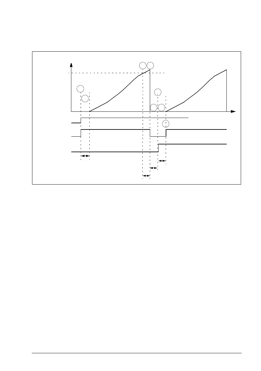
The diagram below illustrates the SPFC powering routine.
1. At start, relay RO 1 is closed and motor 1 is connected to the drive output.
2. The drive waits for the time specified by parameter 8122 PFA START DELAY to
ensure that the contactor (RO 1) has stabilized and then starts modulating from
zero speed. Motor 1 is the speed regulated motor.
3. When the drive output frequency f
out
rises over the start frequency (8109 START
FREQ 1), the start delay for the auxiliary motor (8115 AUX MOT START D) is set.
4. When delay 8115 has elapsed, the drive coasts to stop and relay RO 1 is opened
(motor 1 is disconnected from the drive output).
5. The drive waits for 8122 PFA START DELAY to ensure that the contactor (RO 1)
has stabilized.
6. After delay, 8122 RO 2 is closed and motor 2 is connected to the drive output as
the new speed regulated motor.
7. The drive waits for 8122 PFA START DELAY to ensure that the contactor (RO 2)
has stabilized.
8. After delay 8122, the drive starts modulating from zero speed regulating the
speed of motor 2. RO 1 is closed and motor 1 is connected directly on-line as an
auxiliary motor.
8115 AUX MOT START D
8122 PFA START DELAY
RO 1 / Motor 1
RO 2 / Motor 2
f
out
Start
Motor 1 is speed reg. motor
Motor 2 is speed reg. motor
Motor 1 is aux. motor
1
2
3
4
6
5 7
8
t
8109 START
FREQ 1
8122 PFA START DELAY
8122 PFA START DELAY