Actual signals and parameters 275
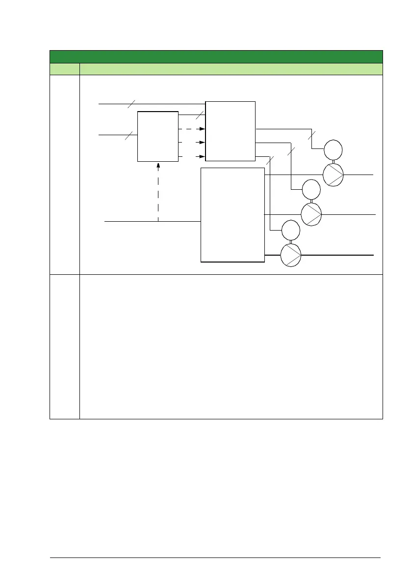
Example: In the diagram below, the pumping station’s outlet flow is controlled by the
measured inlet flow (A).
8122
PFA START DELAY
0.00 … 10.00 s 0.01 s 0.50 s
Sets the start delay for speed regulated motors in the system. Using the delay, the
drive works as follows:
• Switches on the contactor of the speed regulated motor – connecting the motor to
the drive power output.
• Delays motor start for the time 8122 PFA START DELAY.
• Starts the speed regulated motor.
• Starts auxiliary motors. See parameter 8115 AUX MOT START D for delay.
Warning! Motors equipped with star-delta starters require a PFA start delay.
• After the drive relay output switches a motor On, the star-delta starter must switch to
the star-connection and then back to the delta-connection before the drive applies
power.
• So, the PFA start delay must be longer than the time setting of the star-delta starter.
Group 81: PFA control
Code Description Range Resolution Default S
M
3~
M
3~
M
3~
Outlet
Outlet
Outlet
P1
P2
P3
Sewage
tank
Contactors
P1
P2
P3
Mains 3~
3
3
3
3
ACS320
3
3
Inlet pipe
A
pipe1
pipe2
pipe3