274 Actual signals and parameters
5 = DI5 – Enables the Interlock function, and assigns a digital input (starting with DI5)
to the interlock signal for each PFA relay. These assignments are defined in the
following table and depend on:
• The number of PFA relays (number of parameters 1401…1403 and 1410) with value
= 31 (PFA).
• The Autochange function status (disabled if 8118 AUTOCHNG INTERV = 0, and
otherwise enabled).
8121
REG BYPASS CTRL
0…1 1 0
Selects the Regulator by-
pass control. When
enabled, the Regulator
by-pass control provides
a simple control mecha-
nism without a PID regu-
lator.
• Use the Regulator by-
pass control only in
special applications.
0 = NO – Disables the
Regulator by-pass
control. The drive
uses the normal PFA
reference: 1106
REF2 SELECT.
1 = YES – Enables the
Regulator by-pass
control.
• The process PID
regulator is
bypassed.
Actual value of PID is used as the PFA reference (input). Normally EXT REF2 is
used as the PFA reference.
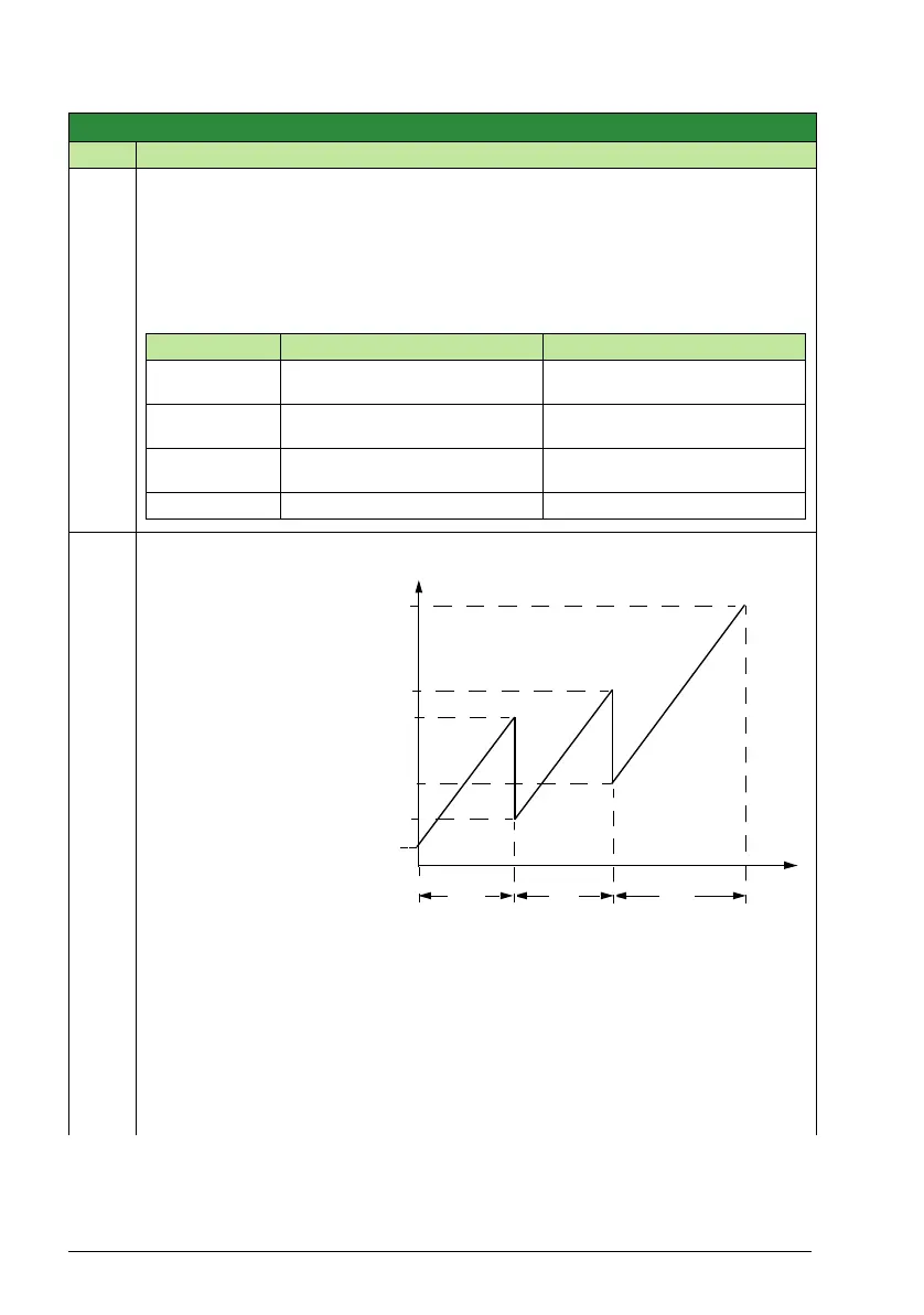
• The drive uses the feedback signal defined by 4014 FBK SEL (or 4114) for the
PFA frequency reference.
• The figure shows the relation between the control signal 4014 FBK SEL (or 4114)
and the speed regulated motor’s frequency in a three-motor system.
Group 81: PFA control
Code Description Range Resolution Default S
No. PFA relays Autochange disabled (8118) Autochange enabled (8118)
0 DI1…DI4: Free
DI5: Speed Reg Motor
Not allowed
1 DI1…DI4: Free
DI5: Speed Reg Motor
DI1…DI4: Free
DI5: First PFA Relay
2 Not allowed DI1…DI4: Free
DI5: First PFA Relay
3…5 Not allowed Not allowed
f
MAX
A = No auxiliary motors running
B = One auxiliary motor running
C = Two auxiliary motors running
A
f
MIN
BC(%)
f
OUT
8112
8113
8110
8109
4014