264 Actual signals and parameters
8111
START FREQ 3
0.0 … 500.0 Hz 0.1 Hz 60.0
Sets the frequency limit used to start the third auxiliary motor.
• See parameter 8109 START FREQ 1 1for a complete description of the operation.
The third auxiliary motor starts if:
• Two auxiliary motors are running.
• ACS320 output frequency exceeds the limit: 8111 START FREQ 3 + 1 Hz.
• Output frequency stays above the relaxed limit (8111 START FREQ 3 - 1 Hz) for at
least the time: 8115 AUX MOT START D.
8112
LOW FREQ 1
0.0 … 500.0 Hz 0.1 Hz 25.0
Sets the frequency limit used to stop the first auxiliary motor. The first auxiliary motor
stops if:
• First auxiliary motor is running
alone.
• ACS320 output frequency
drops below the limit:
8112 LOW FREQ 1 - 1.
• Output frequency stays below
the relaxed limit
(8112 LOW FREQ 1 + 1 Hz)
for at least the time: 8116
AUX MOT STOP D.
After the first auxiliary motor
stops:
• Output frequency increases
by the value =
(8109 START FREQ 1) -
(8112 LOW FREQ 1).
• In effect, the output of the speed regulated motor increases to compensate for the
loss of the auxiliary motor.
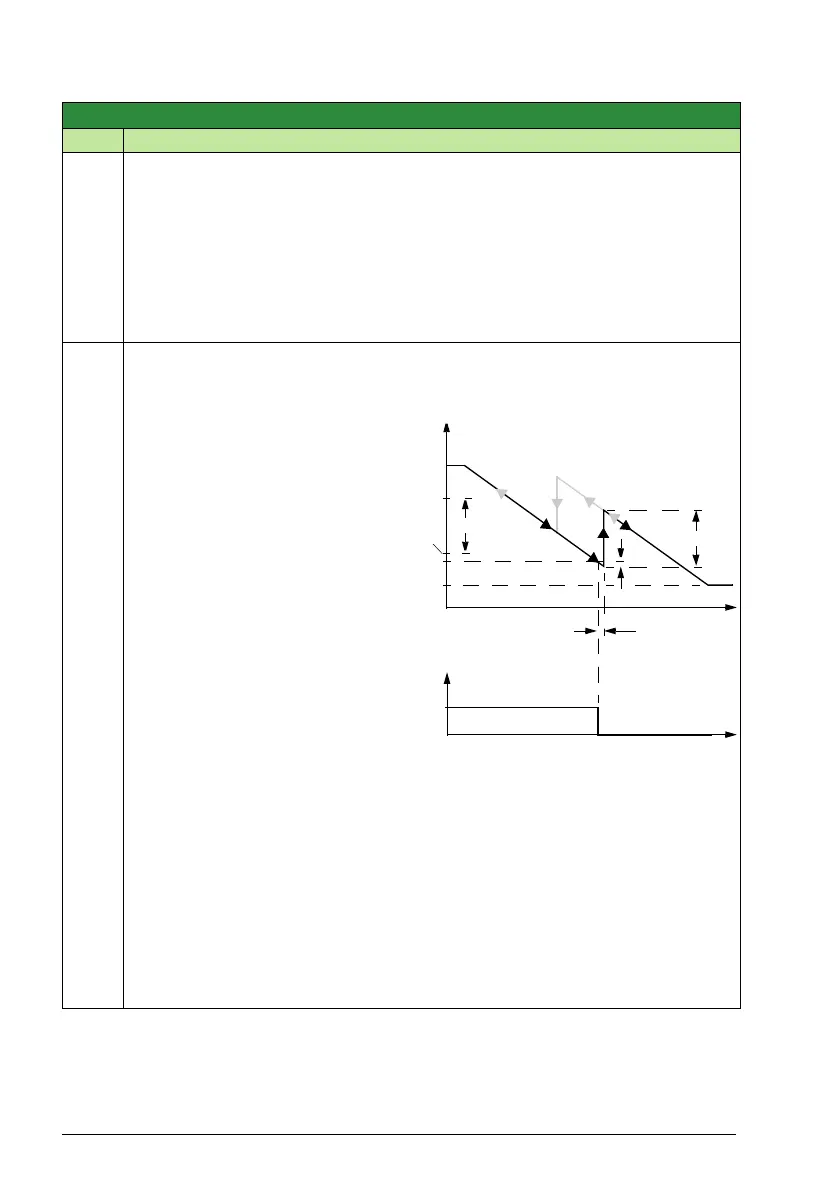
See the figure, where:
•A = (8109 START FREQ 1) - (8112 LOW FREQ 1)
• B = Output frequency decrease during the stop delay.
• C = Diagram showing auxiliary motor’s run status as frequency decreases (1 = On).
• Grey path = Shows hysteresis – if time is reversed, the path backwards is not the
same. For details on the path for starting, see the diagram at 8109 START FREQ 1.
Note: Low Frequency 1 value must be between:
•(2007 MINIMUM FREQ).
• 8109 START FREQ 1
Group 81: PFA control
Code Description Range Resolution Default S
t
B
f (Hz)
f
MAX
f
MIN
t
1
0
C
A
A
8112
8109
(8112)- 1
8116