Actual signals and parameters 183
1608
START ENABLE 1
-5…7 1 4
Selects the source of the start enable 1 signal.
Note: Start enable functionality differs from the run enable functionality.
0 = NOT SEL – Allows the drive to start without an external start enable signal.
1 = DI1 – Defines digital input DI1 as the start enable 1 signal.
• This digital input must be activated for start enable 1 signal.
• If the voltage drops and de-activates this digital input, the drive will coast to stop
and show alarm 2021 START ENABLE 1 MISSING on panel display. The drive
will not start until start enable 1 signal resumes.
2…5 = DI2…DI5 – Defines digital input DI2…DI5 as the start enable 1 signal.
• See DI1 above.
7 = COMM – Assigns the fieldbus Command word as the source for the start enable 1
signal.
• Bit 2 of the Command word 2 (parameter 0302 FB CMD WORD 2) activates the
start disable 1 signal.
• See fieldbus user’s manual for detailed instructions.
-1 = DI1(INV) – Defines an inverted digital input DI1 as the start enable 1 signal.
-2…-5 = DI2(INV)…DI5(INV) – Defines an inverted digital input DI2…DI5 as the start
enable 1 signal.
• See DI1(INV) above.
Group 16: System controls
Code Description Range Resolution Default S
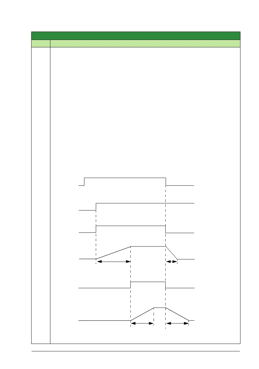
Drive started
START/STOP
COMMAND
Relay energized
Relay
de-energized
Damper open
Damper
time
Damper
closing
time
STARTED
RELAY STATUS
DAMPER
STATUS
Damper
closed
RUN ENABLE SIGNAL
from the damper end
switch when the
damper is fully opened.
MOTOR STATUS
Acceleration
time
Deceleration
time
START ENABLE
SIGNAL
Damper
closed
opening
Group 10: Start/Stop/Dir
1608 & 1609
Group 14: Relay outputs
1601
22032202