206 Actual signals and parameters
3009
BREAK POINT
FREQ
1 … 250 Hz 1 35 Hz
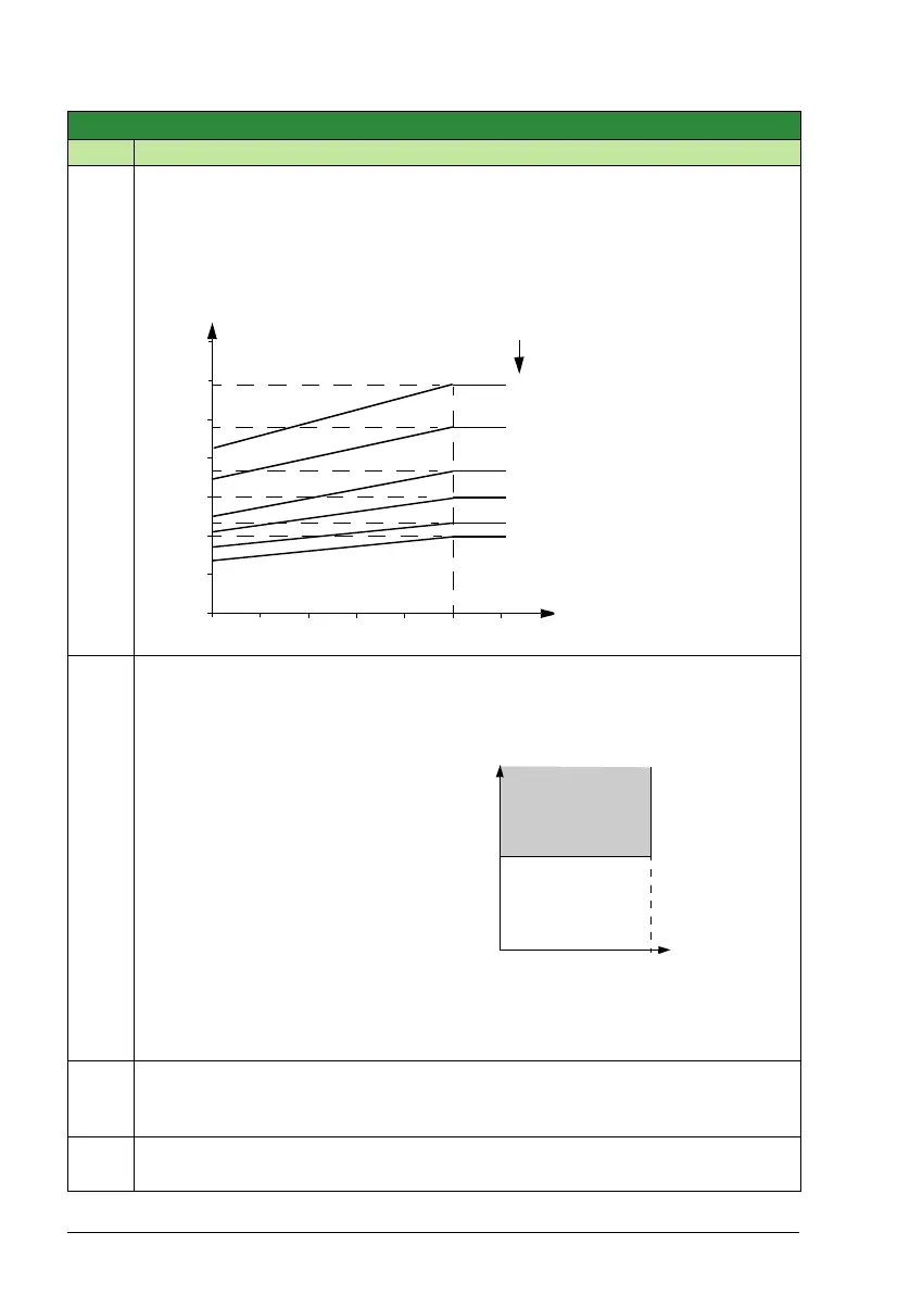
Defines the load curve together with parameters 3007 MOT LOAD CURVE and 3009
BREAK POINT FREQ.
Example: Thermal protection trip times when parameters 3006 MOT THERM TIME,
3007 MOT LOAD CURVE and 3008 ZERO SPEED LOAD have default values.
3010
STALL FUNCTION
0…2 1 35 Hz
Selects how the drive reacts to a motor stall condition. The protection wakes up if the
drive has operated in a stall region (see the figure below) longer than the time set by
parameter 3012 STALL TIME.
0 = NOT SEL – Protection is inactive.
1 = FAULT – Drive trips on fault 0012 MOTOR STALL and the motor coasts to stop.
2 = ALARM – Drive generates alarm 2012 MOTOR STALL.
3011
STALL FREQUENCY
0.5 … 50.0 Hz 0.1 Hz 20.0 Hz
This parameter sets the frequency value for the Stall function. Refer to the figure
above.
3012
STALL TIME
10 … 400 s 1 s 20 s
This parameter sets the time value for the Stall function.
Group 30: Fault functions
Code Description Range Resolution Default S
60 s
3.5
3.0
2.5
2.0
1.5
1.0
0.5
0
0 0.2 0.4 0.8 1.0 1.2
I
O
/I
N
f
O
/f
BRK
90 s
300 s
600 s
0.6
180 s
A
∞
I
O
= Output current
I
N
= Nominal motor current
f
O
= Output frequency
f
BRK
= Break point frequency
A = Trip time
User defined limit =
2003 MAX CURRENT
Current (A)
0.95
·
User defined limit
Stall region
Par. 3011
f