Actual signals and parameters 267
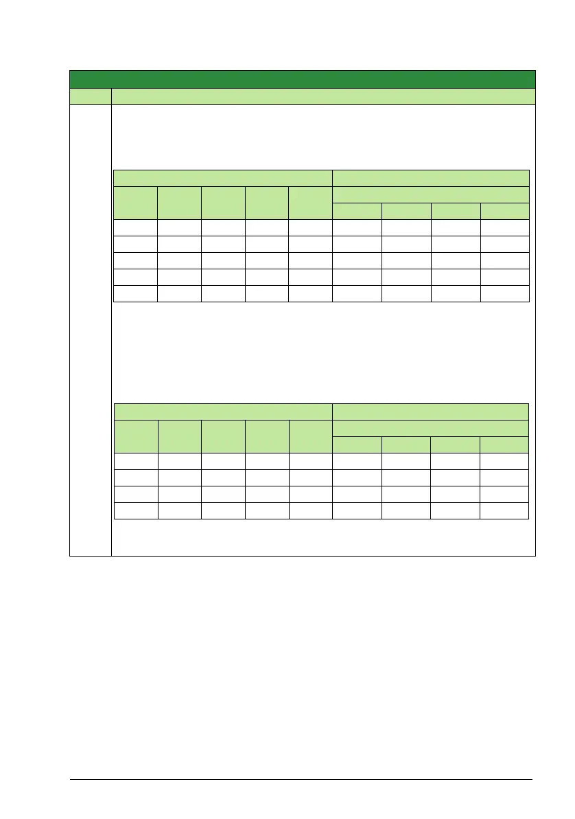
The table below shows the PFA motor assignments for some typical settings in the
relay output parameters (1401…1403 and 1410), where the settings are either = 31 (),
or =X (anything but 31), and where the Autochange function is disabled (8118
AUTOCHNG INTERV = 0).
The table below shows the PFA motor assignments for some typical settings in the
relay output parameters (1401…1403 and 1410), where the settings are either = 31 (),
or =X (anything but 31), and where the Autochange function is enabled (8118
AUTOCHNG INTERV > 0).
Group 81: PFA control
Code Description Range Resolution Default S
Parameter setting Relay assignment
1401 1402 1403 1410 8117 Autochange disabled
RO1 RO2 RO3 RO4
31 X X X 1 Aux. X X X
31 31 X X 2 Aux. Aux. X X
31 31 31 X 3 Aux. Aux. Aux. X
X 31 31 X 2 X Aux. Aux. X
31 31 X X 1* Aux. Aux. X X
* = One additional relay output for the PFC that is in use. One motor is in “sleep” when the other
is rotating.
Parameter setting Relay assignment
1401 1402 1403 1410 8117 Autochange enabled
RO1 RO2 RO3 RO4
31 31 X X 1 PFA PFA X X
31 31 31 X 2 PFA PFA PFA X
X3131X 1 X PFAPFA X
31 31 X X 0** PFA PFA X X
** = No auxiliary motors, but the Autochange function is in use. Working as a standard PID-
control.