Fieldbus control 339
* = Active low
For the 0xxxx registers:
• Status is always readable.
• Forcing is allowed by user configuration of the drive for fieldbus control.
• Additional relay outputs are added sequentially.
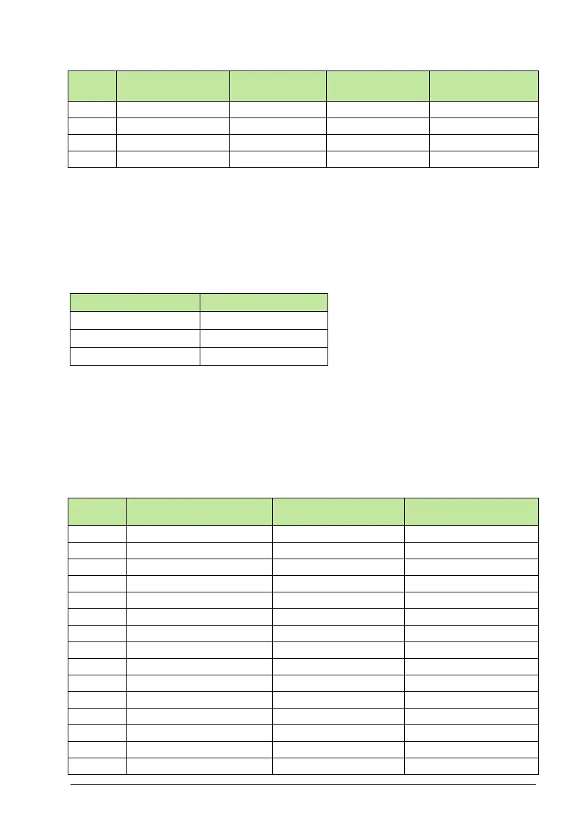
The drive supports the following Modbus function codes for coils:
1xxxx Mapping – Modbus Discrete Inputs. The drive maps the following
information to the 1xxxx Modbus set called Modbus Discrete Inputs:
• Bit-wise map of the
STATUS WORD (selected using parameter 5305 EFB CTRL
PROFILE). The first 32 inputs are reserved for this purpose.
• Discrete hardware inputs, numbered sequentially beginning with input 33.
The following table summarizes the 1xxxx reference set:
00033 relay output 1 Relay Output 1 Relay Output 1 Relay Output 1
00034 relay output 2 Relay Output 2 Relay Output 2 Relay Output 2
00035 relay output 3 Relay Output 3 Relay Output 3 Relay Output 3
00036 relay output 4 Relay Output 4 Relay Output 4 Relay Output 4
Function Code Description
01 Read coil status
05 Force single coil
15 (0x0F Hex) Force multiple coils
Modbus
Ref.
Internal Location
(All Profiles)
(5305 = 0 or 2)
(5305 = 1)
10001 – Bit 0 RDY_ON READY
10002 – Bit 1 RDY_RUN ENABLED
10003 – Bit 2 RDY_REF STARTED
10004 – Bit 3 TRIPPED RUNNING
10005 – Bit 4 OFF_2_STA* ZERO_SPEED
10006 – Bit 5 OFF_3_STA* ACCELERATE
10007 – Bit 6 SWC_ON_INHIB DECELERATE
10008 – Bit 7 ALARM AT_SETPOINT
10009 – Bit 8 AT_SETPOINT LIMIT
10010 – Bit 9 REMOTE SUPERVISION
10011 – Bit 10 ABOVE_LIMIT REV_REF
10012 – Bit 11 EXT2 REV_ACT
10013 – Bit 12 RUN_ENABLE PANEL_LOCAL
10014 – Bit 13 N/A FIELDBUS_LOCAL
10015 – Bit 14 N/A EXT2_ACT
Modbus
Ref.
Internal Location
(All Profiles)
(5305 = 0)
(5305 = 1)
(5305 = 2)