Actual signals and parameters 233
2603 IR COMP
VOLT
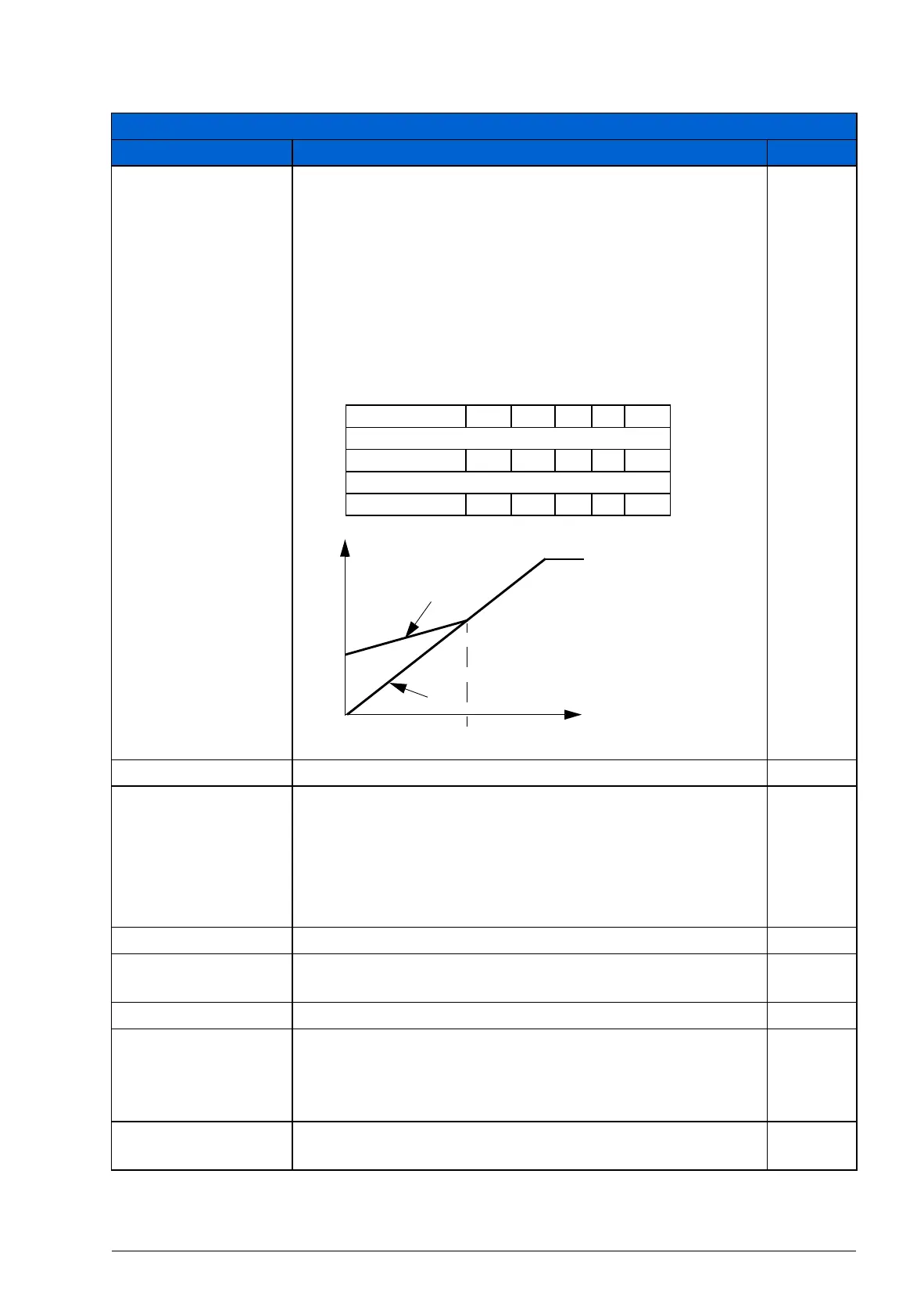
Defines the output voltage boost at zero speed (IR
compensation). The function is useful in applications with a
high break-away torque when vector control cannot be
applied.
To prevent overheating, set IR compensation voltage as low
as possible.
Note: The function can be used only when parameter 9904
MOTOR CTRL MODE setting is SCALAR: FREQ.
The figure below illustrates the IR compensation.
Type
dependent
0.0…100.0 V Voltage boost 1 = 0.1 V
2604 IR COMP
FREQ
Defines the frequency at which the IR compensation is 0 V.
See the figure for parameter 2603 IR COMP VOLT
Note: If parameter 2605 U/F RATIO is set to USER
DEFINED, this parameter is not active. The IR
compensation frequency is set by parameter 2610 USER
DEFINED U1.
80%
0…100% Value in percent of the motor frequency 1 = 1%
2605 U/F RATIO Selects the voltage to frequency (U/f) ratio below the field
weakening point. For scalar control only.
LINEAR
LINEAR Linear ratio for constant torque applications. 1
SQUARED Squared ratio for centrifugal pump and fan applications.
With squared U/f ratio the noise level is lower for most
operating frequencies. Not recommended for permanent
magnet motors.
2
USER
DEFINED
Custom ratio defined by parameters 2610…2618. See
section Custom U/f ratio on page 141.
3
All parameters
No. Name/Value Description Def/FbEq
A
B
A = IR compensated
B = No compensation
Typical IR compensation values:
P
N
(kW) 0.37 0.75 2.2 4.0 7.5
200…240 V units
IR comp (V) 8.4 7.7 5.6 8.4 N/A
380…480 V units
IR comp (V) 14 14 5.6 8.4 7
2603
2604
Motor
voltage
f (Hz)