244 Actual signals and parameters
FAULT The drive trips on fault UNDERLOAD (0017) and the motor
coasts to stop.
Note: Set parameter value to FAULT only after the drive ID
run is performed! If FAULT is selected, the drive may
generate an UNDERLOAD fault during ID run.
1
ALARM The drive generates alarm UNDERLOAD (2011). 2
3014 UNDERLOAD
TIME
Defines the time limit for the underload function. See
parameter 3013 UNDERLOAD FUNC.
20 s
10…400 s Time limit 1 = 1 s
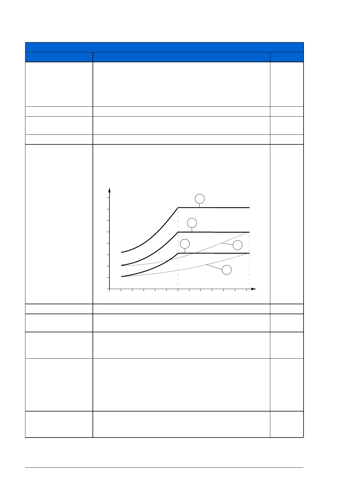
3015 UNDERLOAD
CURVE
Selects the load curve for the underload function. See
parameter 3013 UNDERLOAD FUNC.
1
1…5 Number of the load curve type in the figure 1 = 1
3016 SUPPLY
PHASE
Selects how the drive reacts to supply phase loss, ie when
DC voltage ripple is excessive.
FAULT
FAULT The drive trips on fault SUPPLY PHASE (0022) and the
motor coasts to stop when the DC voltage ripple exceeds
14% of the nominal DC voltage.
0
LIMIT/ALARM Drive output current is limited and alarm INPUT PHASE
LOSS (2026) is generated when the DC voltage ripple
exceeds 14% of the nominal DC voltage.
There is a 10 s delay between the activation of the alarm
and the output current limitation. The current is limited until
the ripple drops under the minimum limit, 0.3 · I
hd
.
1
ALARM The drive generates alarm INPUT PHASE LOSS (2026)
when the DC ripple exceeds 14% of the nominal DC
voltage.
2
All parameters
No. Name/Value Description Def/FbEq
T
M
T
M
= nominal torque of the motor
ƒ
N
= nominal frequency of the motor (9907)
3
2
1
5
4
Underload curve types
70%
50%
30%
80
60
40
20
0
(%)
2.4
·
f
N
f
N
f