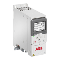
■ Layout
1. Locking tab
2. Option module slot
3. Chassis screw
4. I/O connector
Mechanical installation
See the electrical installation instructions of the drive.
Before you install the BIO-01 option module, make sure that the chassis screw slider is in
the top position. After the option module is installed, tighten the chassis screw and move
the slider to the bottom position.
The BIO-01 option module kit comes with a higher cable clamp plate. Use this cable clamp
plate to ground the wires that connect to the BIO-01 option module.
Electrical installation
The BIO-01 module has removable spring clamp terminals. Use ferrules on the multistranded
conductor ends.
The connection diagram below is valid for the drive equipped with the BIO-01 I/O extension
module when the ABB standard macro is selected (parameter 96.04).
The last column indicates the terminal location: × = base unit, blank = BIO-01 module.
170 BIO-01 I/O extension module

 Loading...