2)
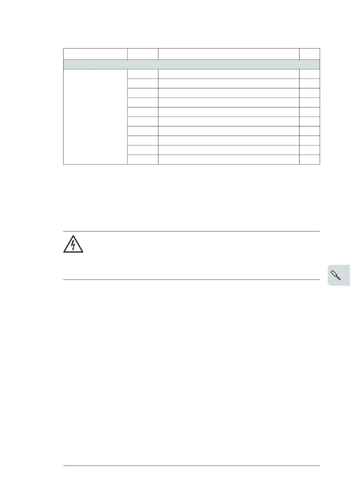
Description
Term.
1)
Connection
Fieldbus connection
+K457 FCAN-01 CANopenDSUB9
See the fielbus adapter
manual.
+K454 FPBA-01 Profibus DPDSUB9
+K469 FECA-01 EtherCATRJ45×2
+K475 FENA-21 Ethernet/IP, Profinet, Modbus TCPRJ45×2
+K470 FEPL-02 Ethernet PowerlinkRJ45×2
+K451 FDNA-01 DeviceNetTerm.block
+K462 FCNA-01 ControlNet8P8C×2
+K490 FEIP-21 Two-port Modbus/IP adapterRJ45×2
+K491 FMBT-21 Two-port Modbus/TCP adapterRJ45×2
+K492 FPNO-21 Two-port Profinet IO adapterRJ45×2
1)
Terminal size: 0.14…1.5 mm
2
(26…16 AWG) Tightening torque: 0.5 N·m (0.4 lbf·ft)
2)
× = base unit, empty = fieldbus module
■ Control cable connection procedure
Do the connections according to the control macro (parameter 96.04) in use.
Keep the signal wire pairs twisted as near to the terminals as possible to prevent inductive
coupling.
WARNING!
Obey the safety instructions of the drive. If you ignore them, injury or death, or
damage to the equipment can occur.
If you are not a qualified electrical professional, do not do installation or
maintenance work.
1.
Stop the drive and do the steps in Electrical safety precautions (page 14) before you
start the work.
2. Strip a part of the outer shield of the control cable for grounding.
3. Use a cable tie to ground the outer shield to the grounding tab. For 360-degree
grounding, use metallic cable ties.
4. Strip the control cable conductors.
5. Connect the conductors to the correct control terminals. Torque the terminals to 0.5 N·m
(4.4 lbf·ft).
6. Connect the shields and grounding wires to the SCR terminal. Torque the terminals to
0.5 N·m (4.4 lbf·ft).
7. Mechanically attach the control cables on the outside of the drive.
Electrical installation – North America 79

 Loading...


