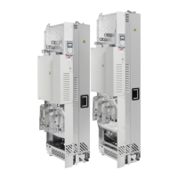
30 Operation principle and hardware description
1 Clear plastic shroud to be attached onto the
drive module input power cabling (a). Lead-
through shroud for side cabling (b). Option
+B051.
8 Output power cable connection terminals
2 Clear plastic shrouds to be attached onto the
drive module output power cabling with option
+B051
9 Grounding terminal for output power cable
shields
3 Clear plastic shroud to be attached on top of
the drive module (lead-through for top cabling)
with option +B051
10 Metallic shroud. With option +H370, the
shroud includes a ground bar.
4 Upper back clear plastic shroud with option
+B051
11 Control unit
5 Lower back clear plastic shroud with option
+B051
12 Pedestal guide plate
6 Front clear plastic shroud with option +B051 13 Telescopic extraction and insertion ramp
7 Input power cable connection terminals
(option +H370)
A Drive module with clear plastic shrouds
mounted (front view)
6
3
+H370
2
4
5
8
10
12
13
1a
1b
7
9
+B051
A
11

 Loading...