48 Guidelines for planning the cabinet installation
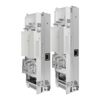
Drive module with option +B051
This diagram shows air baffle positions inside an example cabinet.
1a Air flow to the drive module, max. 40 °C
(104 °F)
3 Drive module
1b Air inlet to the drive module circuit boards and
DC output busbars
4 Disconnector and fuses
2a Vertical air baffle that separates the cool and
hot areas in the cabinet
5 Contactor
2b Horizontal air baffle, see page 136. 6 Drive module control unit
2c Optional air baffle that is needed when there is
no fan on the lower part of the cabinet door
(see 1b on page 38).
7 Air flow out
1
7
L1/U1
L2/V1
L3/W1
PE
T3/W2
T2/V2
T1/U2
3
3
B
B
B – B
A
A
2a
2b
3
2a
2a
4
5
6
2c
2c
3
C
C
2c
2a
2b
2b
A – A
C – C
2b
1b

 Loading...