Guidelines for planning the electrical installation 55
Additional data for calculating the rise time and the peak line-to-line voltage
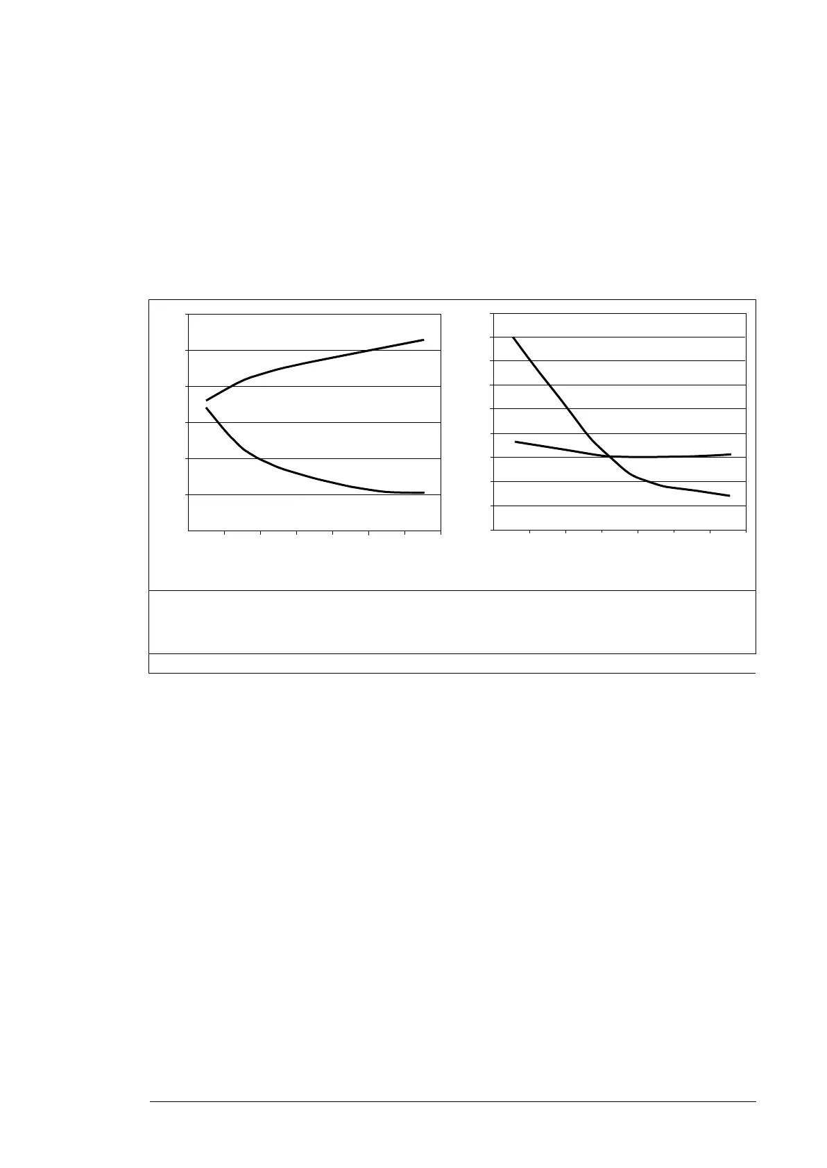
The diagrams below show the relative peak line-to-line voltage and rate of change of
voltage as a function of the motor cable length with and without a du/dt filter in use.
To calculate the actual peak voltage for a certain cable length read the relative Û
LL
/U
N
value from the appropriate diagram and multiply it by the nominal supply voltage (U
N
).
To calculate the actual voltage rise time for a certain cable length read the relative values
Û
LL
/U
N
and (du/dt)/U
N
from the appropriate diagram. Multiply the values by the nominal
supply voltage (U
N
) and substitute into equation t = 0.8 · Û
LL
/(du/dt).
Additional note for common mode filters
Common mode filters are available as plus code option +E208.
Selecting the power cables
General rules
Select the input power and motor cables according to local regulations:
• Select a cable capable of carrying the drive nominal current. See section Ratings
(page 115) for the rated currents.
• Select a cable rated for at least 70 °C (158 °F) maximum permissible temperature of
conductor in continuous use. For US, see Selecting the control cables, page 59.
• The inductance and impedance of the PE conductor/cable (grounding wire) must be
rated according to permissible touch voltage appearing under fault conditions (so that
the fault point voltage will not rise excessively when a ground fault occurs).
• 600 V AC cable is accepted for up to 500 V AC.
Use symmetrical shielded motor cables (see page 58). Ground motor cable shields 360° at
both ends. Keep the motor cable and its PE pigtail (twisted shield) as short as possible to
reduce high-frequency electromagnetic emissions.
Drive with du/dt filter Drive without du/dt filter
I Motor cable length
Û
LL
/U
N
Relative peak line-to-line voltage
du/dt /U
N
Relative du/dt value
Note: ÛLL and du/dt values are approximately 20% higher with resistor braking.
100 200 300
0.0
0.5
1.0
1.5
2.0
2.5
3.0
l (m)
du/dt
U
N
-------------(1/s)
Û
LL
/U
N
Û
LL
/U
N
l (m)
du/dt
U
N
-------------(1/s)
1.0
2.0
5.0
4.0
3.0
1.5
2.5
3.5
4.5
100 200 300
5.5

 Loading...


