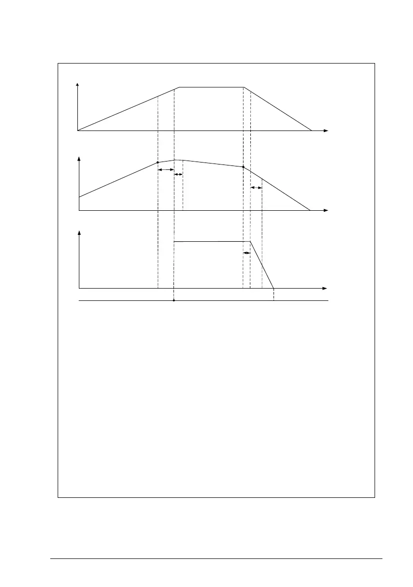
(1) 76.30 Start point 1 - Start speed for the auxiliary motor.
(2) 76.55 Start delay - Delay time to start the auxiliary pump. The pump is
started only when speed of pump 1 is higher or equal to the start speed
(76.30) for the duration mentioned in this parameter.
(3) 76.57 PFC speed hold on - Duration for pump 1 to maintain the speed
momentum. This time is used to compensate the time needed to accelerate
the auxiliary pump to a speed where it produces the flow.
(4) 76.41 Stop point 1 - Stop speed for the auxiliary motor.
(5) 76.56 Stop delay - Delay time to turn off the auxiliary pump when speed of
pump 1 is lower or equal to stop speed (76.41) for the duration mentioned in
this parameter.
(6) 76.58 PFC speed hold off - Time needed to compensate the pump 1
acceleration to the speed that produces flow.
(Demand - represented by the process
PID reference)