230 Parameters
24 Speed reference
conditioning
Speed error calculation; speed error window control
configuration; speed error step.
See the control chain diagram on page 492.
24.01 Used speed
reference
Displays the ramped and corrected speed reference (before
speed error calculation). See the control chain diagram on
page 492.
This parameter is read-only.
-
-30000.00…
30000.00 rpm
Speed reference used for speed error calculation. See par.
46.01
24.02 Used speed
feedback
Displays the speed feedback used for speed error calculation.
See the control chain diagram on page 492.
This parameter is read-only.
-
-30000.00…
30000.00 rpm
Speed feedback used for speed error calculation. See par.
46.01
24.03 Speed error filtered Displays the filtered speed error. See the control chain
diagram on page 492.
This parameter is read-only.
-
-30000.0…
30000.0 rpm
Filtered speed error. See par.
46.01
25
25 Speed control
Speed controller settings.
See the control chain diagrams on pages 493 and 494.
25.01 Torque reference
speed control
Displays the speed controller output that is transferred to the
torque controller. See the control chain diagram on page 493.
This parameter is read-only.
0.0
-1600.0…1600.0% Limited speed controller output torque. See par.
46.03
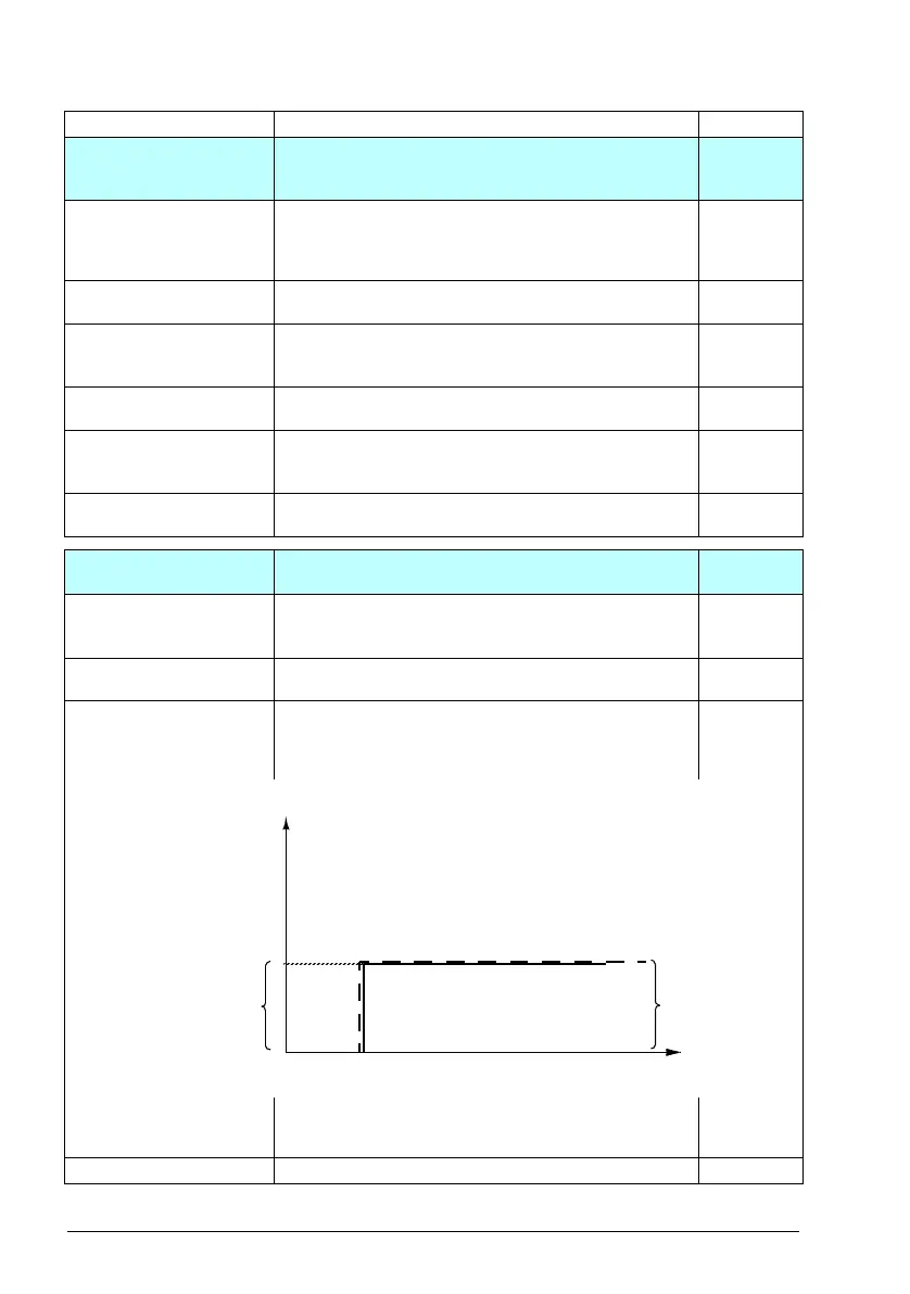
25.02 Speed proportional
gain
Defines the proportional gain (K
p
) of the speed controller. Too
high a gain may cause speed oscillation. The figure below
shows the speed controller output after an error step when
the error remains constant.
5.00
If gain is set to 1, a 10% change in error value (reference -
actual value) causes the speed controller output to change by
10%, ie. the output value is input × gain.
0.00…250.00 Proportional gain for speed controller. 100 = 1
No. Name/Value Description Def/FbEq16
Gain = K
p
= 1
T
I
= Integration time = 0
T
D
= Derivation time = 0
%
Controller
output = K
p
×e
Time
e = Error value
Controller output
Error value