Max.
500 ohm
1…10 kohm
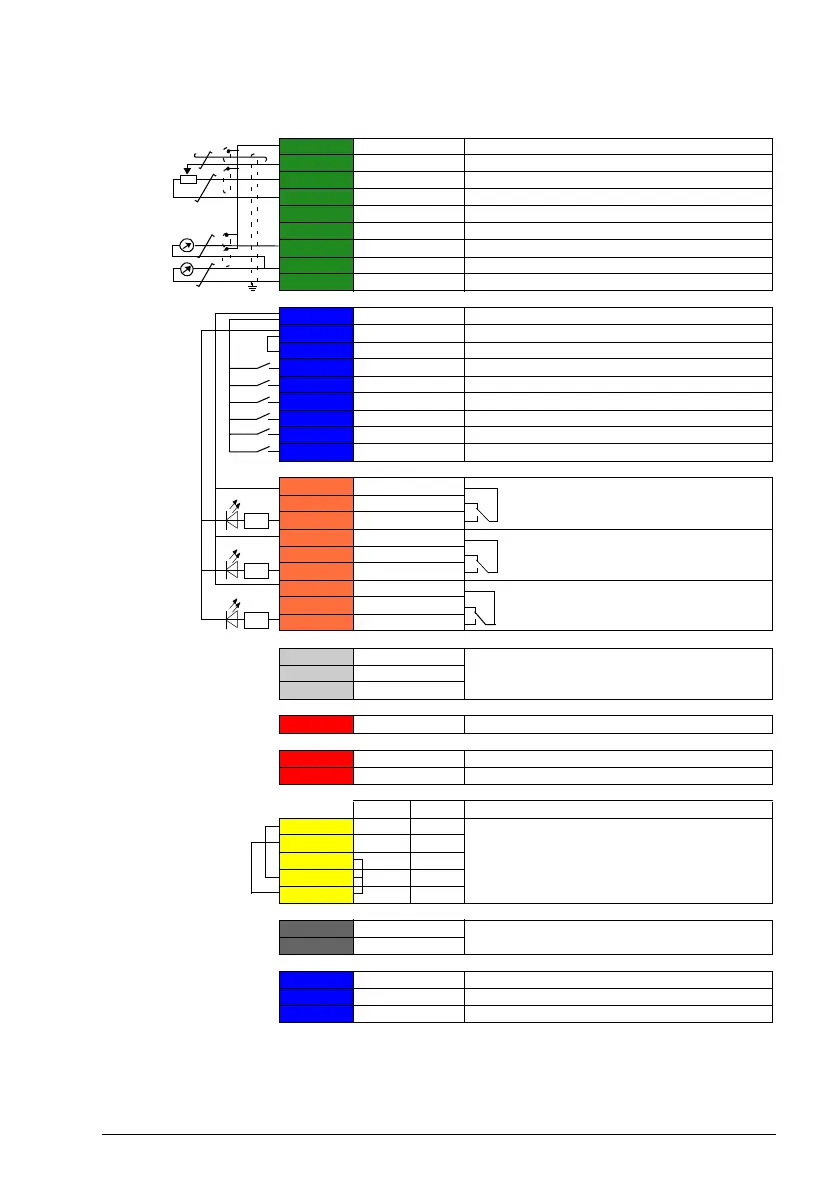
X1 Reference voltage and analog inputs and outputs
1 SCR Signal cable shield (screen)
2 AI1 PID setpoint, 0…10 V
1) 5)
: see 40.16
3 AGND Analog input circuit, common
4 +10V 10 V DC reference voltage
5 AI2 PID feedback, 4...20mA
1) 5)
: see 40.08
6 AGND Analog input circuit, common
7 AO1 Output frequency: 0…20 mA
6)
: see 13.12
8 AO2 Motor current, 0…20 mA
6)
: see 13.22
9 AGND Analog output circuit common
X2, X3 Aux. voltage output and programmable digital inputs
10 +24V Aux. voltage output +24 V DC, max. 250 mA
4)
11 DGND Aux. voltage output common
12 DCOM Digital input common for all
13 DI1 Stop (0) / Start (1) (EXT 1)
5)
: see 20.03
14 DI2 Run enable
5)
: see 20.12 (if 0, drive stops).
15 DI3 EXT1 (0) / EXT 2 (1)
5)
: see 19.11
16 DI4 Not configured
17 DI5 Not configured
18 DI6 Stop (0) / Start (1) (EXT 2): see 20.04
X6,X7, X8 Relay outputs
19 RO1C
Running
6)
: see 10.24
250 V AC / 30 V DC
2 A
20 RO1A
21 RO1B
22 RO2C
PFC1 (1st auxiliary pump)
6)
: see 10.27
250 V AC / 30 V DC
2 A
23 RO2A
24 RO2B
25 RO3C
PFC2 (2nd auxiliary pump)
6)
: see 10.30
250 V AC / 30 V DC
2 A
26 RO3A
27 RO3B
X5 Built-in fieldbus
29 B+
Internal Modbus RTU (EIA-485). See Fieldbus
control through the embedded fieldbus interface
(EFB).
30 A-
31 DGND
(Frame R0...R2)
S100 TERM&BIAS Termination resistor and bias resistor switch
(Frame R3...R8)
S100 TERM Termination resistor switch
S200 BIAS Bias resistor switch
X4
Safety torque off
R0...R2 R3...R
33 - OUT1
Safety torque off function. Factory connection.
Both circuits must be closed for the drive to start.
See Safe torque off function in the drive
hardware manual.
34 SGND OUT2
35 OUT1 SGND
36 IN1 IN1
37 IN2 IN2
X10 24 V AC/DC (frames R6...R8 only)
40 24 V AC/DC- in 24V AC/DC input, for control unit power supply
when external main power is disconnected.
41 24 V AC/DC+ in
X11 Redundant auxiliary voltage output (frames R0...R2)
42 +24 V Aux. voltage output +24 V DC, max. 250 mA
4)
43 DGND Aux. voltage output common
44 DCOM Digital input common for all
3)
R3...R8
3)
3)
2)
7)