186 Parameters
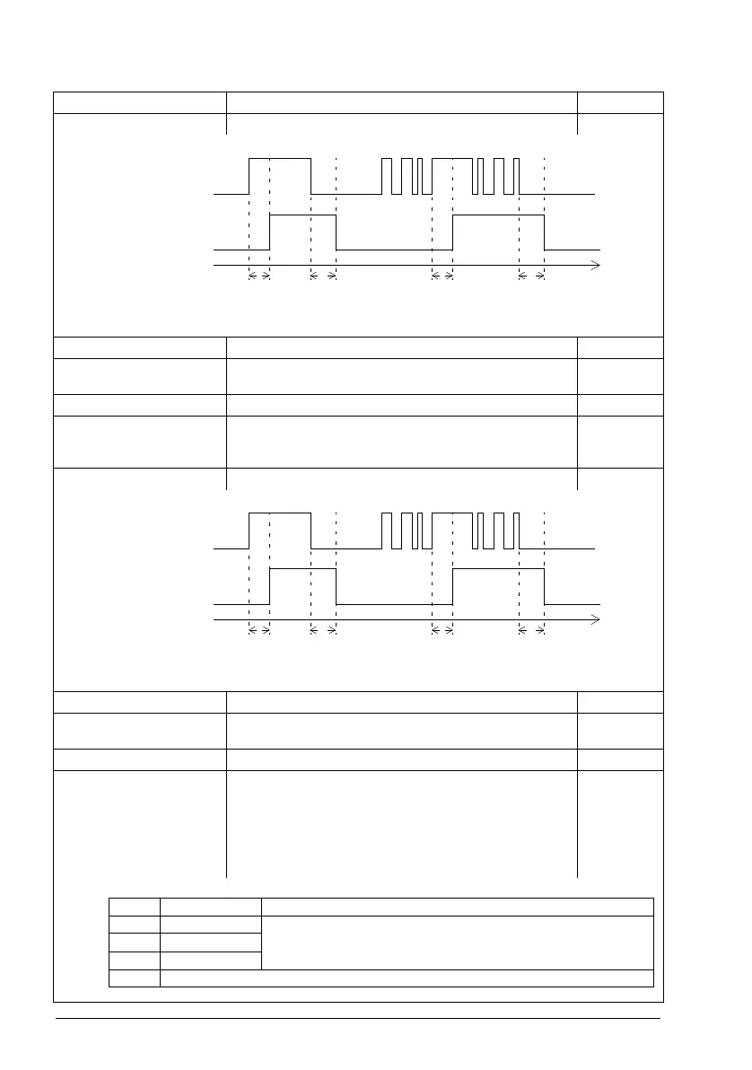
10.28 RO2 ON delay Defines the activation delay for relay output RO2. 0.0 s
t
On
= 10.28 RO2 ON delay
t
Off
= 10.29 RO2 OFF delay
0.0 … 3000.0 s Activation delay for RO2. 10 = 1 s
10.29 RO2 OFF delay Defines the deactivation delay for relay output RO2. See
parameter 10.28 RO2 ON delay.
0.0 s
0.0 … 3000.0 s Deactivation delay for RO2. 10 = 1 s
10.30 RO3 source Selects a drive signal to be connected to relay output RO3.
For the available selections, see parameter 10.24 RO1
source.
Fault (-1)
10.31 RO3 ON delay Defines the activation delay for relay output RO3. 0.0 s
t
On
= 10.31 RO3 ON delay
t
Off
= 10.32 RO3 OFF delay
0.0 … 3000.0 s Activation delay for RO3. 10 = 1 s
10.32 RO3 OFF delay Defines the deactivation delay for relay output RO3. See
parameter 10.31 RO3 ON delay.
0.0 s
0.0 … 3000.0 s Deactivation delay for RO3. 10 = 1 s
10.99 RO/DIO control
word
Storage parameter for controlling the relay outputs e.g.
through the embedded fieldbus interface. To control the relay
outputs (RO) of the drive, send a control word with the bit
assignments shown below as Modbus I/O data. Set the target
selection parameter of that particular data (58.101…58.114)
to RO/DIO control word. In the source selection parameter of
the desired output, select the appropriate bit of this word.
0b0000
No. Name/Value Description Def/FbEq16
1
0
1
0
t
On
t
Off
t
On
t
Off
Status of selected
source
RO status
Time
1
0
1
0
t
On
t
Off
t
On
t
Off
Status of selected
source
RO status
Time
Bit Name Description
0 RO1 Source bits for relay outputs RO1…RO3. See parameters 10.24,
10.27 and 10.30
.
1RO2
2RO3
3…15 Reserved