Parameters 185
Supervision 1 Bit 0 of 32.01 Supervision status (see page 266). 33
Supervision 2 Bit 1 of 32.01 Supervision status (see page 266). 34
Supervision 3 Bit 2 of 32.01 Supervision status (see page 266). 35
Start delay Bit 13 of 06.17 Drive status word 2 (see page 175). 39
RO/DIO control
word bit0
Bit 0 of 10.99 RO/DIO control word (see page 186). 40
RO/DIO control
word bit1
Bit 1 of 10.99 RO/DIO control word (see page 186). 41
RO/DIO control
word bit2
Bit 2 of 10.99 RO/DIO control word (see page 186). 42
PFC1 Bit 0 of 76.01 PFC status (see page 345). 45
PFC2 Bit 1 of 76.01 PFC status (see page 345). 46
PFC3 Bit 2 of 76.01 PFC status (see page 345). 47
PFC4 Bit 3 of 76.01 PFC status (see page 345). 48
Event word 1 Event word 1 = 1 if any bit of 04.40 Event word 1 (see page
170) is 1, that is, if any warning, fault or pure event that has
been defined with parameters 04.43…04.71 is on.
53
User load curve Bit 3 (Outside load limit) of 37.01 ULC output status word (see
page 292).
61
RO/DIO control
word
Maps to corresponding bit in parameter 10.99 RO/DIO control
word. For example, Bit 0 of 10.99 RO/DIO control word
controls RO1, Bit 1 of 10.99 RO/DIO control word controls
RO2, and so on.
62
Other [bit] Source selection (see Terms and abbreviations on page 162). -
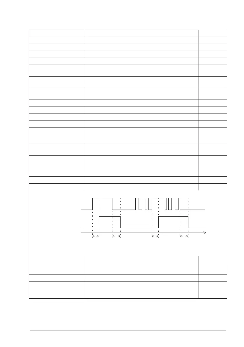
10.25 RO1 ON delay Defines the activation delay for relay output RO1. 0.0 s
t
On
= 10.25 RO1 ON delay
t
Off
= 10.26 RO1 OFF delay
0.0 … 3000.0 s Activation delay for RO1. 10 = 1 s
10.26 RO1 OFF delay Defines the deactivation delay for relay output RO1. See
parameter 10.25 RO1 ON delay.
0.0 s
0.0 … 3000.0 s Deactivation delay for RO1. 10 = 1 s
10.27 RO2 source Selects a drive signal to be connected to relay output RO2.
For the available selections, see parameter 10.24 RO1
source.
Running
No. Name/Value Description Def/FbEq16
1
0
1
0
t
On
t
Off
t
On
t
Off
Status of selected
source
RO status
Time