Program features 87
The figure and table on page 146 show typical KTY84 sensor resistance values as a
function of the motor operating temperature.
See section Implementing a motor temperature sensor connection on page 83.
For the wiring of the sensor, see chapter Electrical installation, AI1 and AI2 as Pt100,
Pt1000, Ni1000, KTY83 and KTY84 sensor inputs (X1) in the Hardware manual of the
drive.
Temperature monitoring using KTY83 sensors
One KTY83 sensor can be connected to an analog input and an analog output on the
control unit.
The analog output feeds a constant excitation current of 1.0 mA through the sensor.
The sensor resistance increases as the motor temperature rises, as does the voltage
over the sensor. The temperature measurement function reads the voltage through
the analog input and converts it into degrees Celsius.
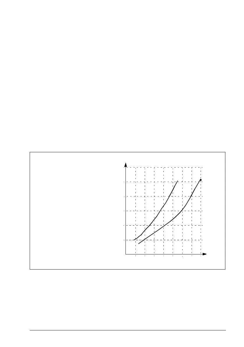
The figure and table below show typical KTY83 sensor resistance values as a
function of the motor operating temperature.
It is possible to adjust the motor temperature supervision limits and select how the
drive reacts when overtemperature is detected.
See section Implementing a motor temperature sensor connection on page 83.
For the wiring of the sensor, see chapter Electrical installation, AI1 and AI2 as Pt100,
Pt1000, Ni1000, KTY83 and KTY84 sensor inputs (X1) in the Hardware manual of the
drive.
1000
2000
3000
Ohm
T (
o
C)
-100
0
0 100 200 300
Scaling
KTY84 KTY83
°C ohm ohm
90 936 1569
110 1063 1774
130 1197 1993
150 1340 2225
KTY83
KTY84