98 Program features
Example of using dead-band in AI1
If,
12.110 AI dead band = 5%
12.15 AI1 unit selection = V
12.18 AI1 max = 10 V
then,
AI dead-band value = 10 * 5% = 0.5 V
AI Hysteresis value = 0.5 * 10% = 0.05 V
Hysteresis negative value = 0.5 - 0.05 = 0.45 V
Hysteresis positive value = 0.5 + 0.05 = 0.55 V
When AI1 input voltage increases, up to 0.55 V, the AI1 actual value (12.11) displays
zero. After AI1 input voltage reaches 0.55 V, the AI1 actual value displays 0.55 V and
continues to display the detected value up to 10 V (12.18).
When AI1 input voltage decreases, the AI1 actual value displays the detected value
up to 0.45 V. From 0.45 V to zero, the AI1 actual value displays Zero.
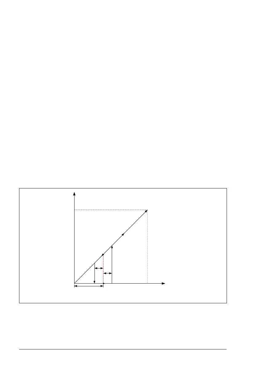
See the timing diagram below:
Dead-band function timing diagram
Settings
Parameter 12.110 AI dead band (page 193)
12.11 AI1 actual value
12.18 AI1 max (V)
12.18 AI1 max (V)
AI input reference
a
0.5
0.55
a - Dead-band value
b - Hysteresis negative value
c - Hysteresis positive value
0.45
b
c