Categorization by frame size and option code
Some descriptions, instructions, technical data and dimensional drawings which concern
only certain brake units are marked with the symbol of the frame size such as 4×R8i. The
marking derives from the quantity and basic construction of the brake chopper modules that
form the brake unit. For example, frame size 2×R8i indicates that the brake unit consists of
two frame size R8i brake chopper modules connected in parallel.
The frame size is marked on the type designation labels. The frame size of each brake
chopper module is also shown in the technical data.
The instructions and technical data which concern only certain optional selections are marked
with option codes (such as +E210). The options included in the drive can be identified from
the option codes on the type designation label.
Use of component designations
Some device names in the manual include the item designation in brackets, for example
[Q20], to make it possible to identify the components in the circuit diagrams of the drive.
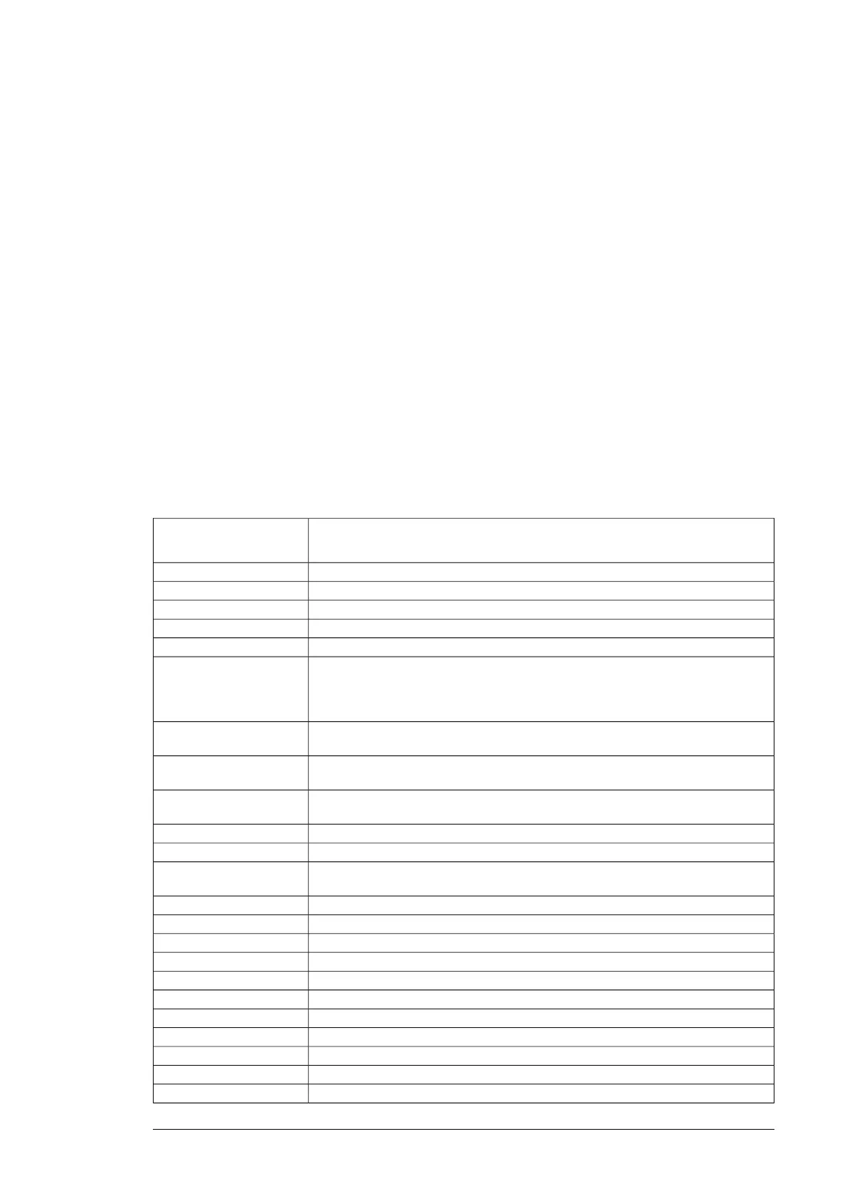
Terms and abbreviations
DescriptionTerm/
Abbreviation
Type of control boardBCON
Type of control unitBCU
Control board for direct-on-line cooling fanBDFC
Module internal power supply boardBDPS
Control and power supply board for speed-controlled cooling fanBFPS
Conducts the surplus energy from the intermediate circuit of the drive to the brake
resistor when necessary. The chopper operates when the DC link voltage exceeds
a certain maximum limit. The voltage rise is typically caused by deceleration
(braking) of a high inertia motor.
Brake chopper
Brake chopper enclosed in a metal frame or housing. Intended for cabinet installa-
tion.
Brake chopper module
Dissipates the drive surplus braking energy conducted by the brake chopper to
heat
Brake resistor
Brake chopper modules and the necessary auxiliary equipment, such as control
electronics, fusing and cabling
Brake unit
Circuit board in which the control program runsControl board
Control board built in a housing (often rail-mountable)Control unit
One section of a cabinet-installed drive. A cubicle is typically behind a door of its
own.
Cubicle
DC circuit between rectifier and inverterDC link
Digital inputDI
Frequency converter for controlling AC motorsDrive
Electromagnetic compatibilityEMC
Diagnostics and panel interface boardFDPI
Optional Ethernet POWERLINK adapter moduleFEPL-01
Optional analog I/O extension moduleFIO-11
Rittal Flat-PLS, a busbar system for standard, commercially available flat busbarsFlat-PLS
Physical size of the drive or power moduleFrame, frame size
DC circuit between rectifier and inverterIntermediate circuit
Converts direct current and voltage to alternating current and voltage.Inverter
Introduction to the manual 13

 Loading...


