• a backup for the regenerative supply unit is needed.
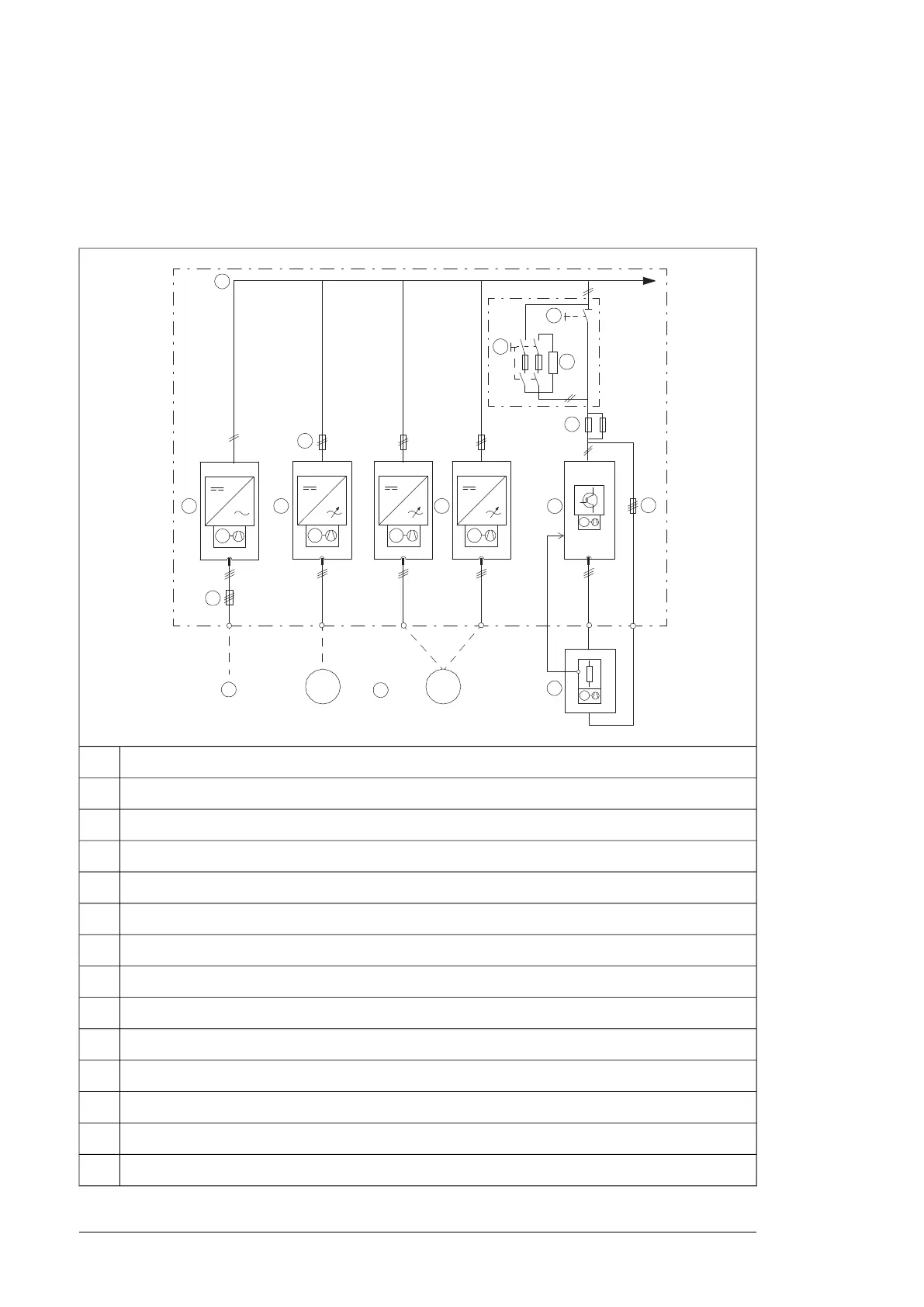
Simplified main circuit diagram of the drive system
This diagram shows a typical common DC bus drive system.
0
000
0
a
0
a
0
0
t°
AC supply1
Input (AC) fuses2
Supply unit3
DC bus4
Inverter DC fuses (with or without a DC switch/disconnector)5
Inverter units (in this example, one of the two units consists of two inverter modules connected in parallel)6
Brake chopper fuses7
Brake unit8
Brake resistors9
Brake resistor fuses10
Motor(s)11
DC switch/disconnector12
Charging circuit switch with fuses13
Charging resistors14
16 Operation principle and hardware description

 Loading...


