Overview of power and control connections
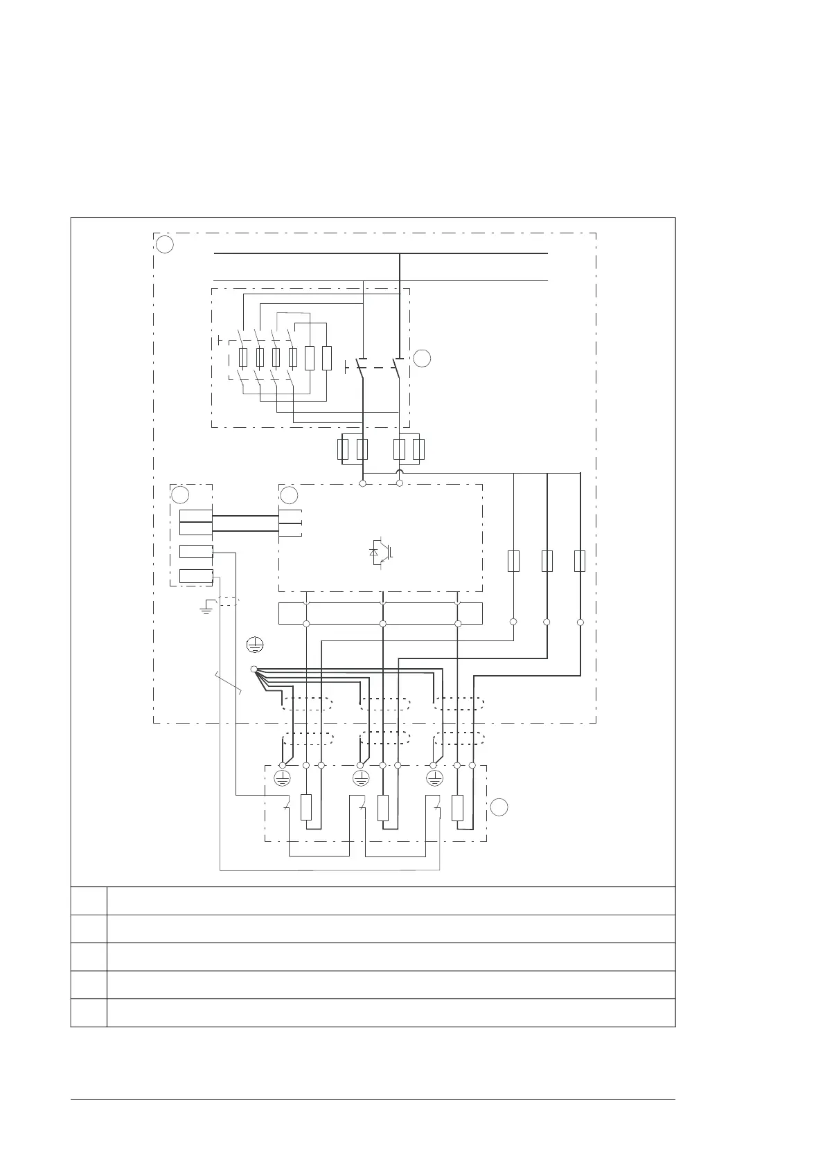
The diagram below shows the power and control connections of the brake unit consisting
of one 3-phase brake module. For parallel-connected brake modules, the brake resistors
are connected to each brake module also as shown below.
9 :8
'&'&
3(
'&
'&
t
t
t
5 5 5
9
',
97
95
9
9
5 5 5
Brake module cubicle1
DC switch/disconnector with charging circuit2
Control unit3
Brake module4
Brake resistors5
22 Operation principle and hardware description

 Loading...


