■ Definitions
Nominal voltage.U
N
Minimum allowed resistance value of the brake resistor per one phase of the brake module.R
min
Maximum resistance value of the brake resistor per one phase of the brake module.R
max
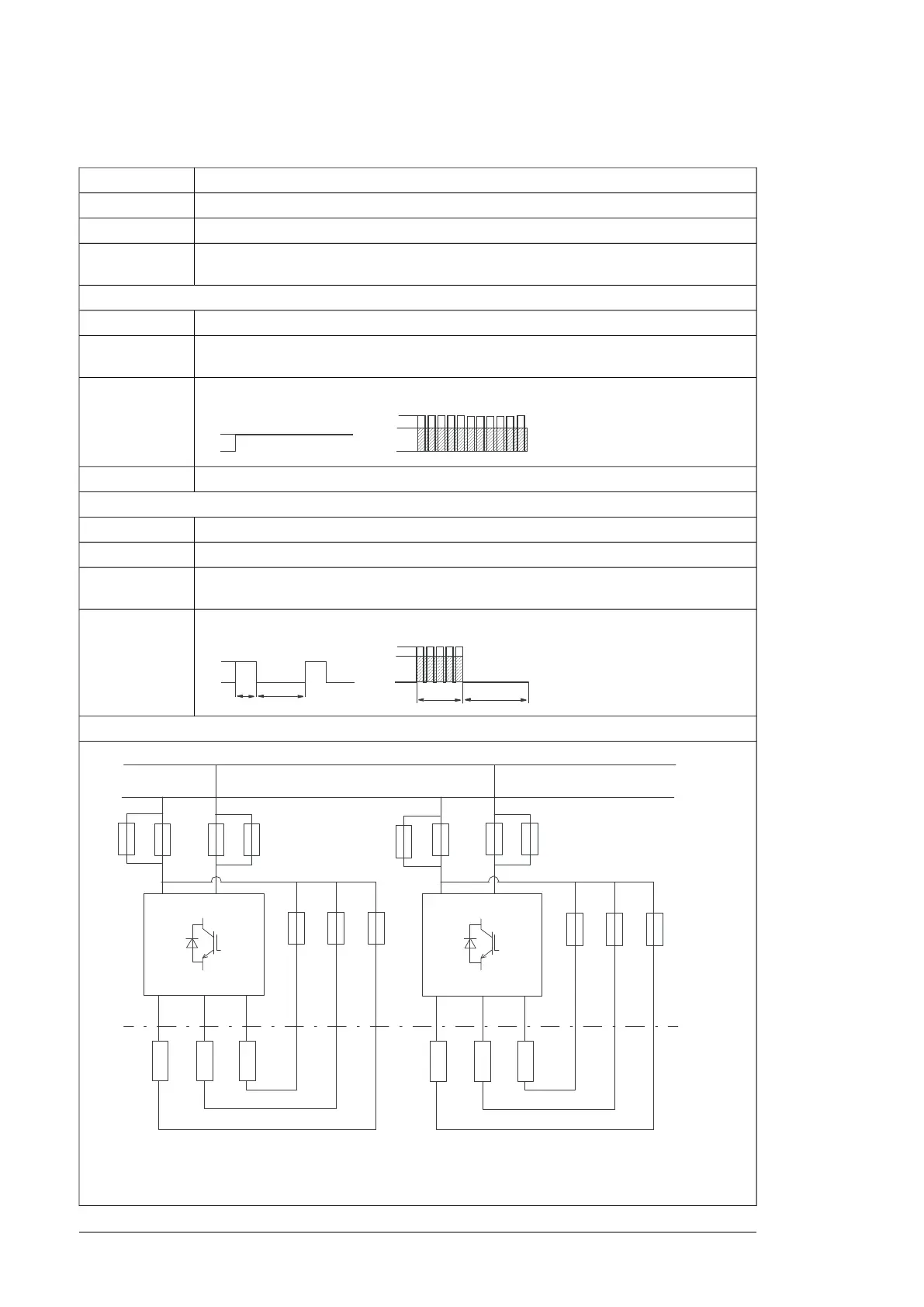
Connect one resistor per brake chopper module phase. For example, a brake unit of frame
size 2×R8i includes two brake chopper modules -> 2 × 3 resistors are needed.
Note:
No-overload use
Input current. Input current with R
min
is given in the type designation label.
I
1
Output current. This is indicated in the type designation label as 3x the value with R
min
given
in this table.
I
2
Maximum continuous braking power per brake unit.P
cont.max
Apparent power.S
n
Cyclic load (1 min / 5 min)
Peak brake current (DC) per brake chopper module phase.I
max
Input current.I
dc
Total rms DC current per brake unit phase during a period of 1 minute with braking power
P
br
.
I
rms
Short term braking power per brake unit allowed for one minute every 5 minutes.P
br
PLQ PLQ
P
EU
PLQ
PLQ
I
PD[
I
UPV
Example: Brake unit with two parallel brake chopper modules
'&
'&
I
I
I
I
I
I
I
I
I
I
9 :8 9 :8
98 Technical data

 Loading...


