■ Connectors X50…X53
The cabinet builder must arrange an auxiliary voltage of 230 V AC (or 115 V AC with option
+G304) to connector X50 to power the electronics of the power module. Also, the cabinet
builder must arrange an auxiliary voltage of 230 V AC to connector X50 to power the main
circuit interface board of the module during charging.
There is an internal power supply (BDPS) in the module that produces 24 V DC from the
auxiliary voltage for the internal circuit boards. The 24 V DC voltage is available on X53 and
it can be used to power the BCU control unit. It is not allowed to use the 24 V DC output on
terminal X53 for any other purpose than for powering the BCU control unit. If the unit consists
of parallel-connected R8i modules, ABB recommends to use an external 24 V DC supply
to power the BCU control unit.
If a direct-on-line fan (option +C188) is used, the user must connect the fan supply (400 V AC
50 Hz or 60 Hz) to the module control connector [X50.1]. If an internal heating element
(option +C183) is used, the user must connect the supply for the heating element to the
module control connector [X50.7].
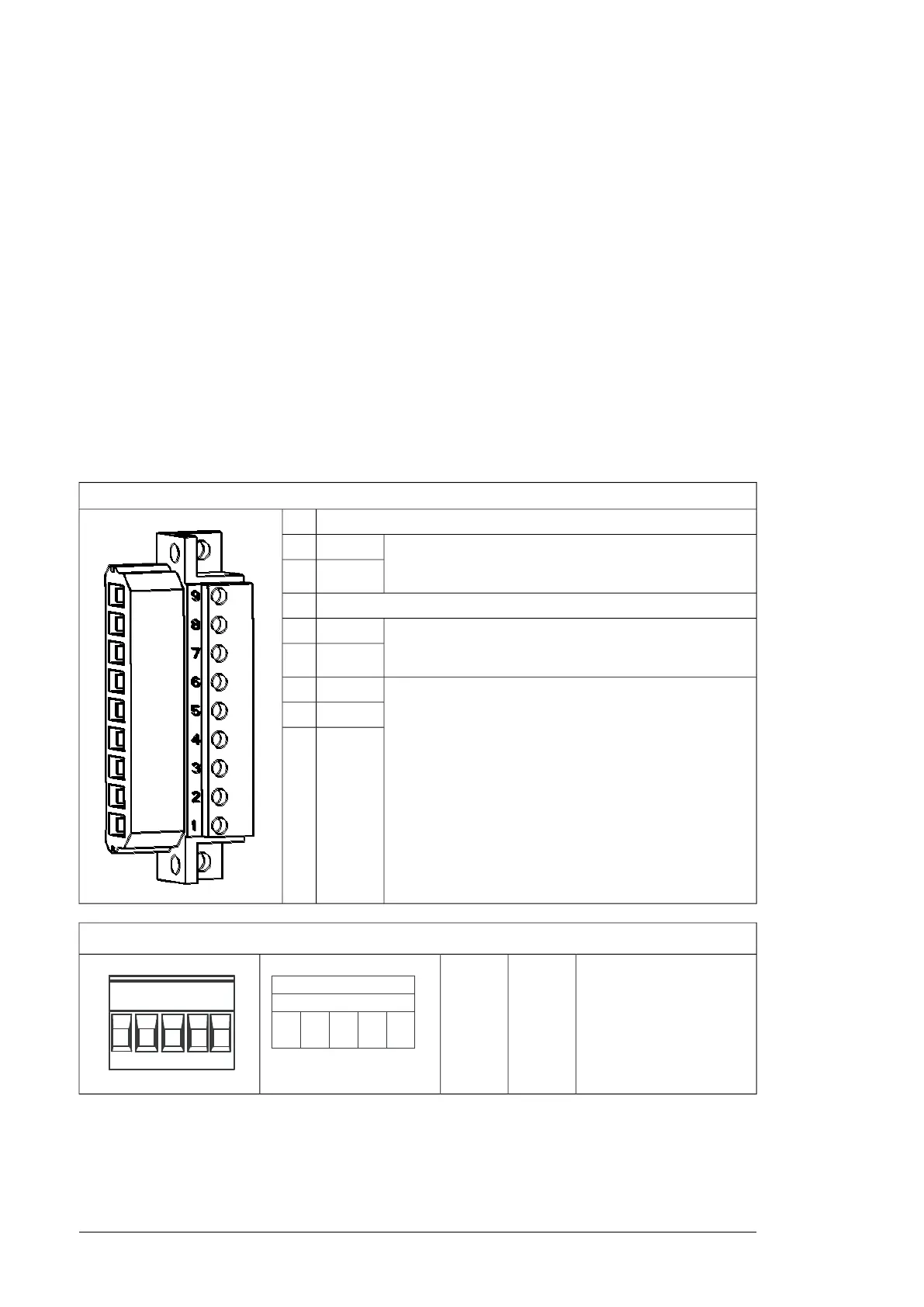
Connector X50
Not in use.9
115/230 V AC (50/60 Hz) input for optional heating element
(+C183). The cabinet builder must connect this when the
option is in use.
N8
L7
Not in use.6
115/230 V AC 50 Hz input for internal power supply (BDPS)
(115 V AC 60 Hz with option +G304). The cabinet builder
must connect this.
N5
L4
400 V AC (50/60 Hz) supply for optional DOL (direct-online)
cooling fan (option +C188). The cabinet builder must connect
this when the option is in use.
Note: In modules without +C188, the DOL wiring is present
but not in use.
W3
V2
U1
Connectors X51, X52, X53
Not in use.STO
OUT
X51
18 Operation principle and hardware description

 Loading...


