Brake unit control devices
Each brake chopper module employs a dedicated control unit (BCU) that contains the BCON
board with basic I/Os and slots for optional modules. A fiber optic link connects the BCU to
the brake chopper module.
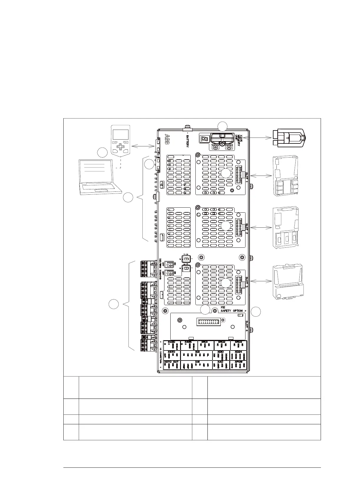
■ Overview of the control connections of the BCU control unit
The diagram shows the control connections and interfaces of the BCU control unit.
1
2
3
4
5
6
7
F
X
X
F
X
X
F
X
X
X
8
CLOSE
9
10
Control panel.7Analog and digital I/O extension modules and
fieldbus communication modules can be inserted
into slots 1, 2 and 3.
1
2
3
Fiber optic links to power modules (inverter,
supply, brake or converter)
8Memory unit4
Ethernet port. Not in use.9Slot 4 for RDCO-0x5
Safety option interface. Only in use for the invert-
er units.
10Terminal blocks.6
Operation principle and hardware description 23

 Loading...


